Network redundancy provides multiple paths for traffic so that network communications remain functional even during a failure. A network failure can occur due to a faulty device/link or a network attack (e.g., DDoS, man-in-the-middle attacks, ARP spoofing, etc.). Relying on just one device/link can lead to a single point of failure, limiting the inside network communications or even those to the internet.
By deploying additional switches and adding extra links between them, the network can resist different potential failures. However, adding redundant links between switches create Layer 2 switching loops, and a loop prevention mechanism must be implemented.
Download the guide and refer back to it at any time!
In this article, we will provide:
- the reasons for implementing a redundant network,
- the benefits and the side-effects of a redundant deployment,
- and a solution for avoiding Layer 2 loops in a switched topology.
If you're ready to jump to Part Two in this series, go here.
If you're looking to purchase new switches, view some of our comparison guides:
- Comparing the Cisco 3560, 3850, and 9300 Switches
- Deep Dive Comparison: Cisco's Catalyst 6500 & 6800 Switches
- Head-To-Head With the Cisco Catalyst 4500 vs. 9400 Chassis Switches
- Cisco Switch: The Ultimate Guide for Enterprises
Physical Redundancy in a Network
Physical redundancy is the simplest way to eliminate the possibility of a single point of failure. Building a reliable switched network requires additional switches and redundant links between devices, which is especially essential for real-time voice and video services.
When a switch fails, the redundant one continues the switching responsibilities, providing unnoticeable network interruptions. The same applies to the physical links, so when the active link fails, everything continues through the redundant, and the network stays operational.
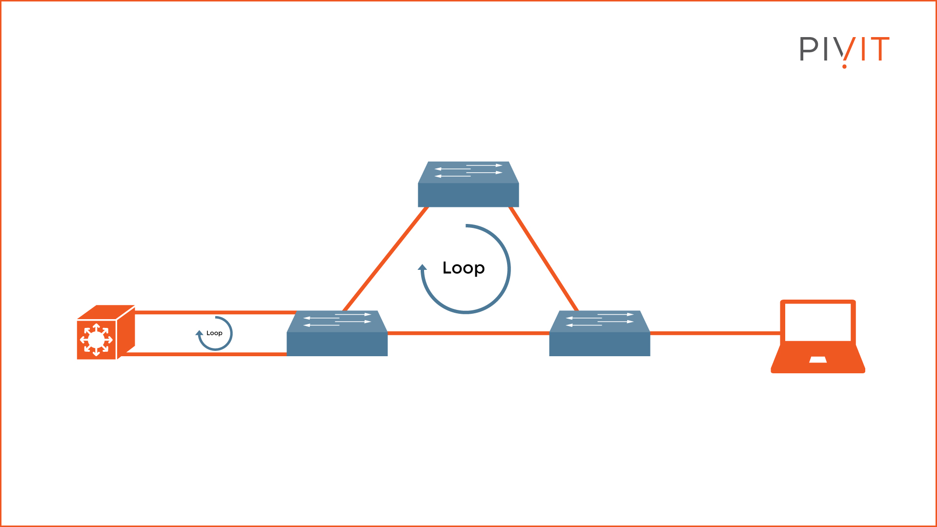
However, as shown in the image above, physical loops lead to network instability, decreased functionality, and increased overhead. Over a period, these physical loops make the network slow, idle, or even non-functional.
Hardware Options For You
We make it easy for you to find the switches that will ensure you fix looping issues. Reach out to us to share the project you are currently working on. Alternatively, click below to see our extensive list of hardware options.

Redundant Topology – The Issue
Redundancy issues can be challenging to spot. The reason is that the network may still function, but you experience slower network behavior, usually during peak hours, and then everything goes back to normal, and so the cycle continues. You might think that a large amount of traffic during peak hours is the reason for that behavior instead of a redundancy issue.
So, what happens when a network lacks a mechanism to avoid bridging loops? Three things can go wrong, namely:
- broadcast storms,
- multiple frame transmissions,
- and MAC database instability.
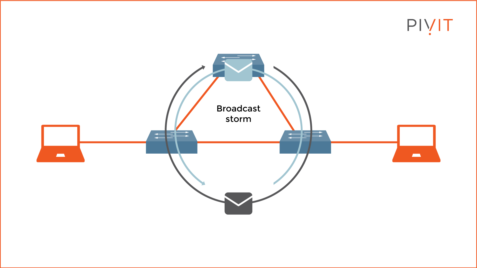
A broadcast storm can easily occur in a network because switches, by default, flood broadcast, multicast, and unknown unicast frames endlessly (see the example topology above).
By replicating such traffic, the network gets flooded, and the number of frames continuously rises until the switches can no longer handle them properly. This is when you experience slow network behavior or even total network communication failure.
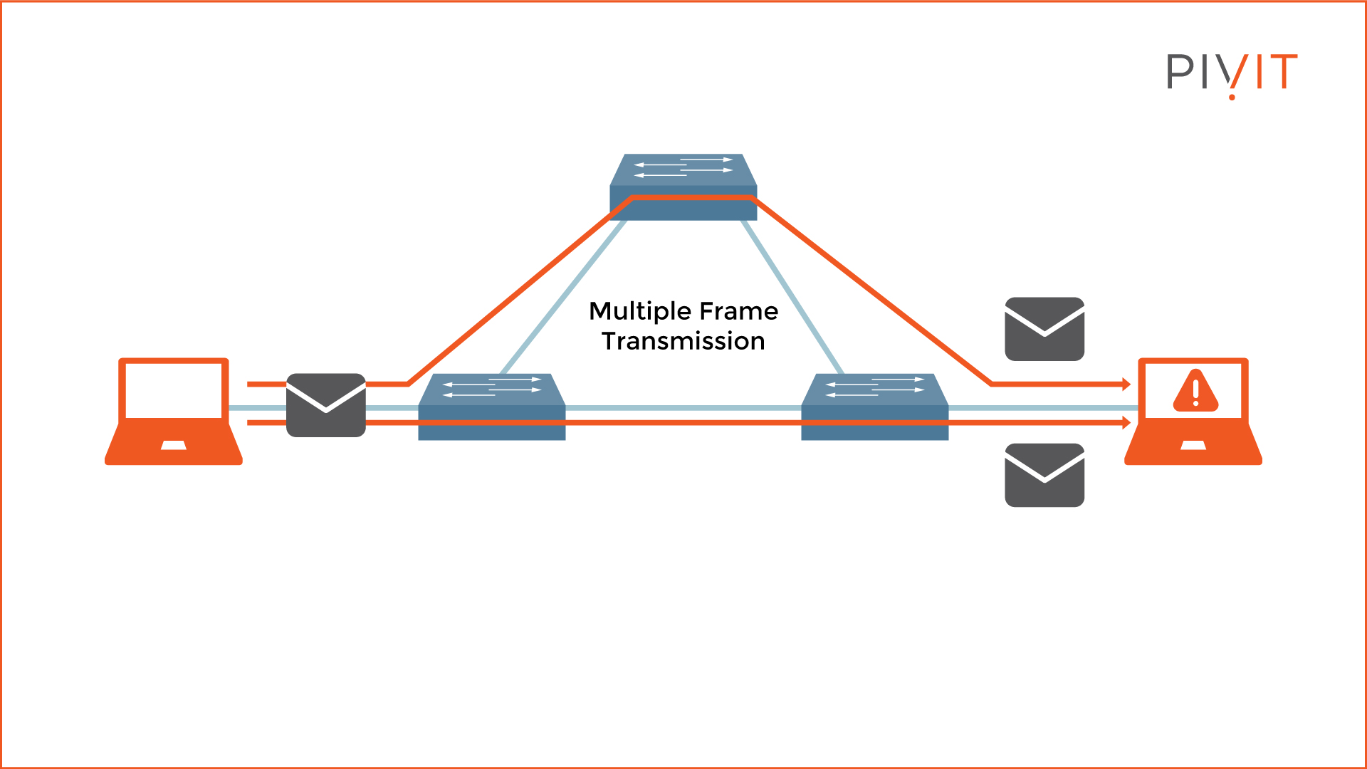
Multiple frame transmissions occur when multiple copies of a single unicast frame arrive at the same destination host, which can cause unrecoverable errors (see the example topology above).
In normal network behavior, a single copy of a unicast frame should be received by a destination host. However, multiple frame transmissions are a problem without a proper loop-free mechanism.
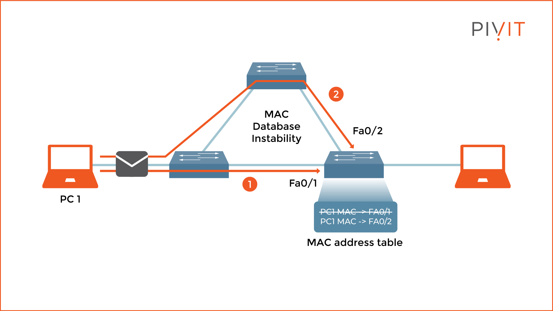
Last but not least, MAC database instability occurs when frames sent by a sender arrive at the recipient through different paths and get received on different interfaces. Consequently, the switch relearns the MAC address of the sender and rewrites that information in the MAC address table for each received copy of the same frame. This leads to incorrect information being stored and utilizing most of the resources for MAC address rewrites.
Do you have older switches that are coming up on their end-of-sale date? Roll those right onto our OneCall maintenance strategy, where you get dedicated spares so you can protect your critical infrastructure.

Spanning Tree Protocol – The Solution
The solution to prevent Layer 2 loops comes from a protocol called Spanning Tree Protocol (STP). It was developed in the 1980s as a prevention mechanism that offers loop-free redundant topology regardless of the number of redundant switches or links in the topology. STP is enabled in Cisco switches by default, so no extra configuration is required to avoid loops.
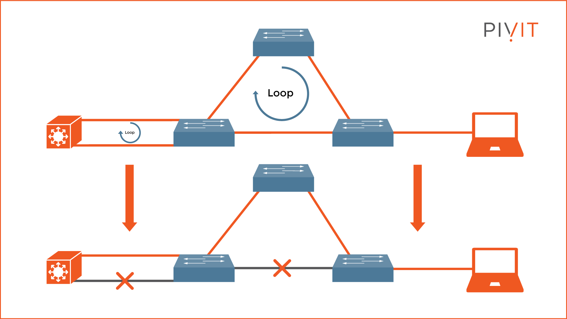
The main goal of STP is to disable as many redundant links as necessary in the topology but still provide active links to each part of the network (see the example topology above). However, if there is a connectivity problem and an active link fails, STP activates some logically disabled ports and provides an alternative path to the same destination.
STP operations are possible by exchanging a special message between the switches called Bridge Protocol Data Units (BPDUs). Several steps are involved in the STP process calculations:
- Elect a root bridge
- Elect a root port for each non-root switch
- Elect a designated port for each segment
- Port transitioning to either forwarding or blocking state
Let's go through each step and find out what happens in each.
1. Electing a Root Bridge
Only one root bridge is elected in a network. The election process is based on a parameter called "bridge ID," which is unique for each switch participating in the STP calculations.
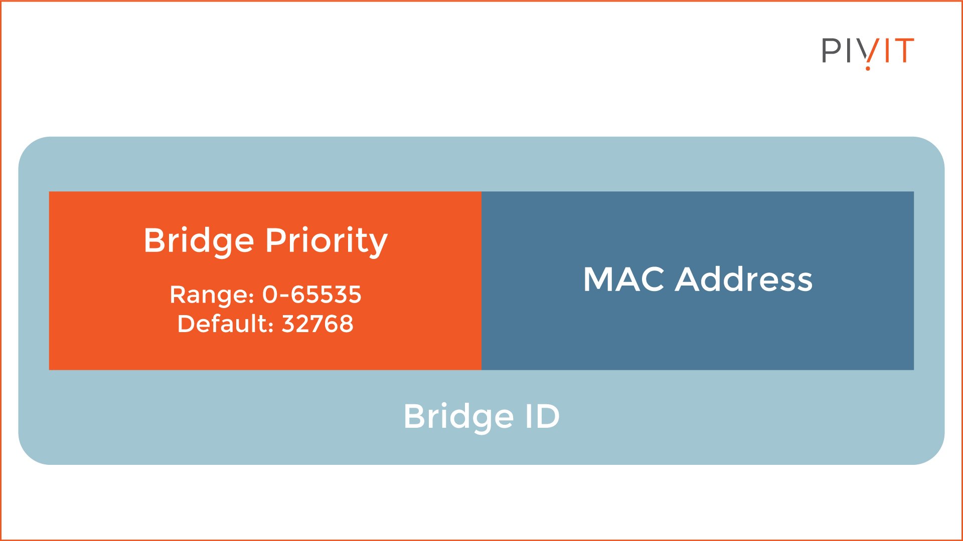
As you can see from the image above, the bridge ID contains two parameters called "bridge priority" and "MAC address." The bridge priority is 32768 by default and can be a value between 0 and 65535, while the MAC address represents the MAC address of the switch.
When switches exchange their Bridge IDs through the BPDU messages, the one with the lowest Bridge ID becomes the Root Bridge. The way the calculation works is that the lower the value is, the higher the priority. The bridge priorities are compared, but if they are the same, the MAC addresses are compared.
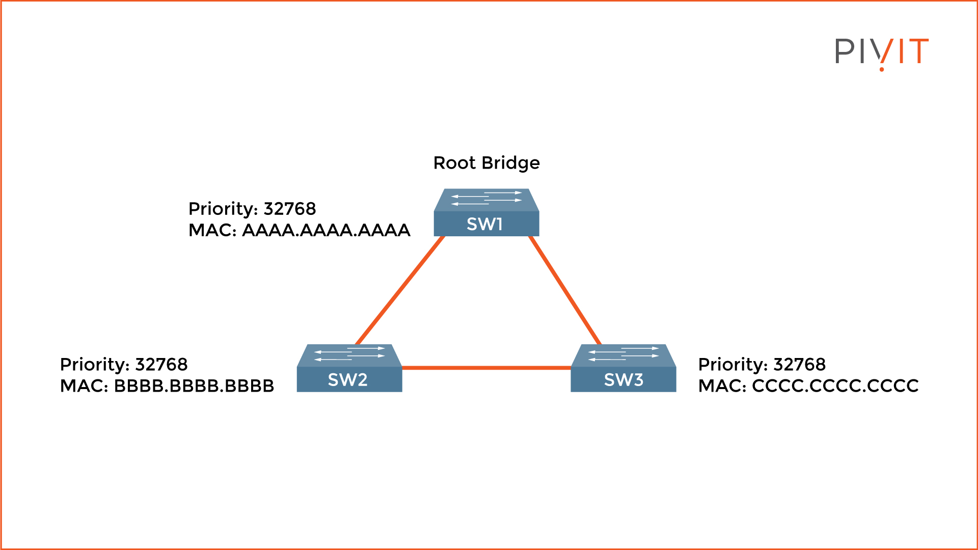
In the image above, SW1 is elected as a root bridge since they all have the same priority value, but it uses the lowest MAC address.
2. Elect a Root Port for Each Non-Root Switch
On each non-root switch (SW2 and SW3), only one port is elected as a root port. This is the port with the best path to the root bridge. The calculation is based on the speed of each link. However, the bandwidth parameter is not used, but STP's values (the higher the interface bandwidth, the lower the cost). Again, the smaller the value is, the better the cost is.
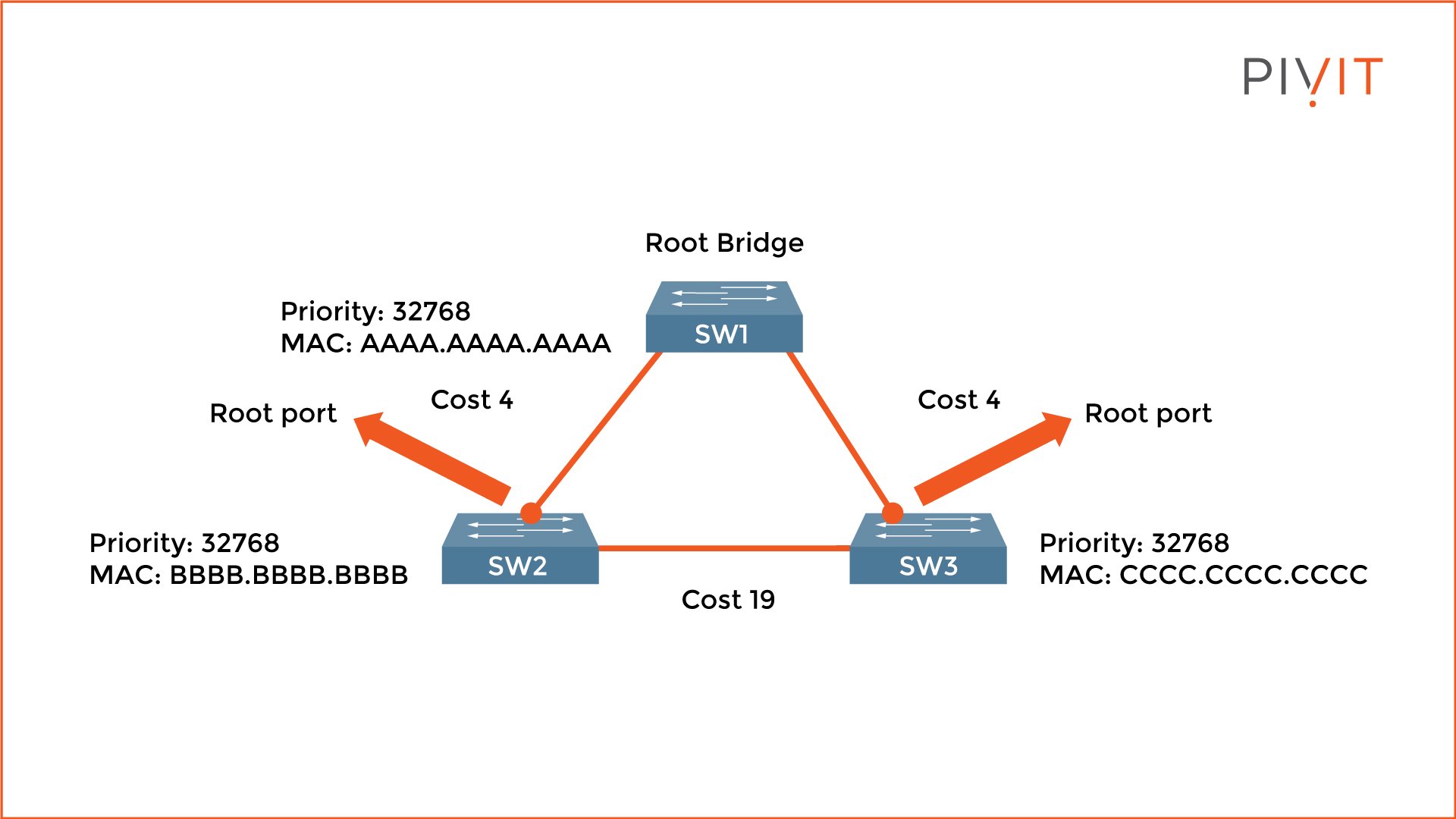
In the image above, both uplinks on SW2 and SW3 have the best cost value (4 is better than 19) and are elected as root ports.
3. Elect a Designated Port for Each Segment
On each segment in the network, a designated port is elected. Since only one port can be a designated port on a segment, the port on the other side is either a root or a blocked port. Again, the calculation is based on the lowest path cost toward the root bridge.
All ports are designated ports on the root bridge since they are closest. Keep in mind that when the cost is the same, the comparison continues to the bridge ID.
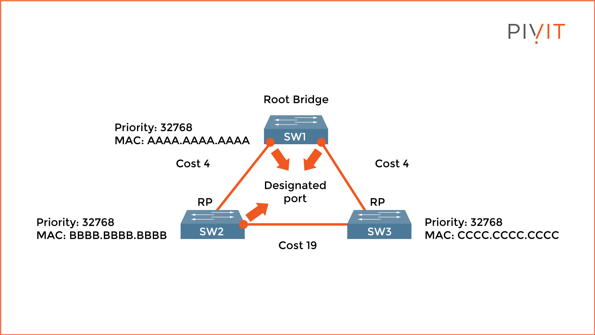
In the image above, both ports on the root bridge (SW1) are elected designated ports. SW2's port (SW2 and SW3 segment) is elected a designated port due to a lower MAC address than SW3.
4. Port Transitioning to Either Forwarding or Blocking State
The last step of the STP election process is the state assignment on all ports included in the STP calculation. When everything is finished, the root ports and designated ports transition to the forwarding state, which allows sending and receiving data traffic. The other ports, also called non-designated ports, stay in the blocking state (blocked port).
When in a blocking state, the ports are logically disabled by STP but listen for network changes. As a result, when an active port (root or designated) fails, the blocked port activates and provides uninterrupted network communications.
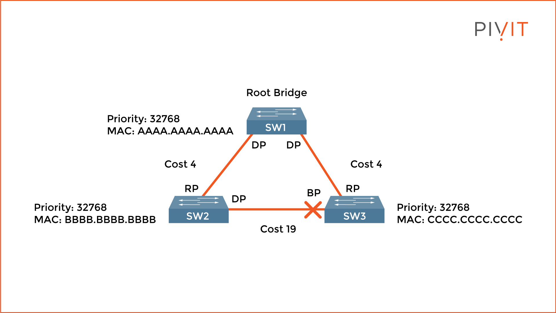
From the image above, SW3's port that belongs to the segment connecting to SW2 gets blocked. The only active links are between SW1 and SW2, and SW1 and SW3. When SW2 needs to communicate with SW3, the data traffic goes through SW1 (the root bridge), and even though this path is not optimal, no loops exist in the network.
STP is essential for networks to function properly. Although STP is enabled by default on Cisco switches, other protocols should be implemented to achieve better optimization. Check out Part 2 of this article to get an overview of the other types of protocols and their benefits.
Short on team resources to configure your gear? We know teams can sometimes be stretched thin and don't always have the resources or headcount to configure your gear at the speed you'd like.
PivIT's EXTEND offering can step in to augment your team and remote in to configure your gear with expert-level engineers (SmartHands | EXTEND). If you need someone on-site, we have field services ready at a moment's notice.
