-1.png)
Generic Routing Encapsulation (GRE) is a tunneling protocol for exchanging encapsulated data packets over an established tunnel. In other words, GRE creates a virtual point-to-point link between two devices in separate networks that need to communicate with each other.`
The whole process consists of three steps:
- Encapsulating packets on one side
- Sending them across the tunnel to the other side
- Forwarding them to the destination (after de-encapsulation).
Now, you might get the wrong impression that GRE is a type of VPN for exchanging data over a public network and to a certain point this is true. However, GRE as a protocol is quite simple and limited in certain ways, and yet still brings some very important advantages when properly deployed. Therefore, you will not get the same benefits as a VPN, but it will still help you when two devices need to exchange data.
In this article, we will provide an overview of the GRE protocol, discuss the reasons why to use it, the benefits it provides, as well as take a quick look at one configuration example to get a better idea of its functionality. First, let's get a better understanding of the GRE protocol.
Overview of GRE
The main goal when using the GRE protocol is to establish a tunnel between two L3 devices, usually routers, which will show as being directly connected. The virtual link or the tunnel might be established internally, between different locations in the same network, or between devices across the internet.
One important note about GRE is that it does not support any security features to protect the data being exchanged. As a result, any data exchanged over the internet might be at risk of being intercepted and misused by a third party.
Furthermore, GRE uses IP protocol 47 and can be used together with other protocols. For example, you can use GRE with IPsec VPN to exchange data that provides security over everything being sent across the tunnel.
GRE supports unicast, multicast, and broadcast traffic. The only limitation is not being able to secure that data, since there is no support for encryption.
GRE Encapsulation
When enabling GRE, a tunnel is always established between the L3 devices. One of these two devices is the source of the tunnel, while the other one is the destination. The data must first be encapsulated before it is sent over the tunnel.
The whole idea behind this protocol is based on the encapsulation and de-encapsulation process. GRE encapsulates data packets that use one protocol inside packets of another protocol. This allows packets that are not supported by a network (e.g. different routing protocols) to be carried out from one side to another from within packets that are supported.
After encapsulation, the data is sent across the GRE tunnel. Any routers in between the source and destination devices of the tunnel will not open the encapsulated packets but only use the header information to forward them to the tunnel endpoint. After de-encapsulation, the router will forward the data to the destination.
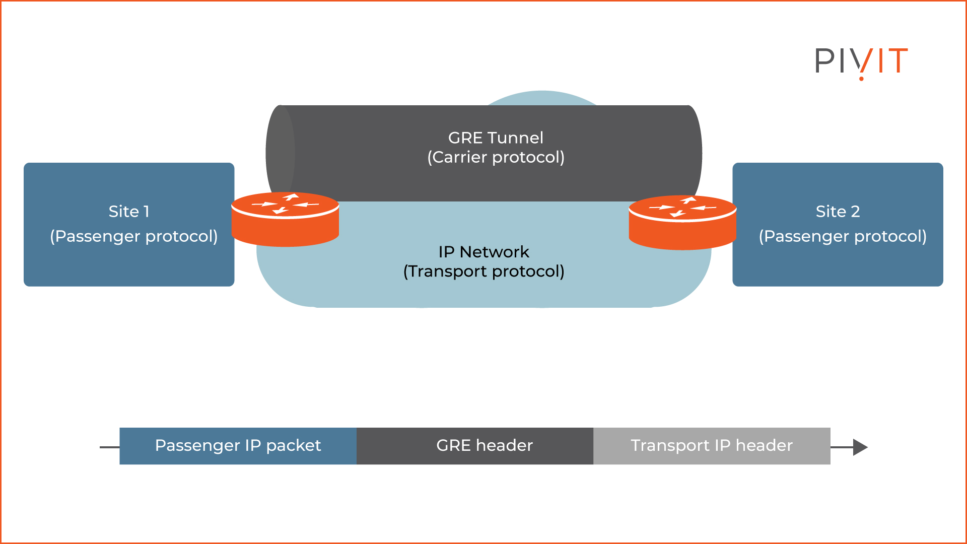
The image above illustrates the two sites that need to exchange data over the internet. The protocols that they use can be anything such as OSPF packets. However, for the packets to be transported from one site to another, they must be encapsulated into a GRE protocol. This is called the carrier protocol.
Once the data is encapsulated, it will be transported over the internet by a transport protocol such as IPv4. For this process to work, GRE adds additional headers.
What Does the GRE Header Contain?
GRE adds two headers on top of the existing packet header during the encapsulation process. The first GRE header is 4 bytes long and is used to identify the L3 protocol and might contain some additional information. The second header is the IP header, which is 20 bytes long and encapsulates the original packet’s header and payload.
As a result, the packet is forwarded based on the destination address in the additional GRE IP header. Only the routers at each end of the GRE tunnel will use the original IP header of the packet.
GRE Configuration Example
Configuring a GRE tunnel is a straightforward process. The whole implementation consists of just a few configuration steps on each router creating the tunnel.
If you run into any issues, have trouble configuring GRE, or simply need an extra set of hands to help in the configuration, we have a team ready to step in to configure your network through our SmartHands offering.

Example Topology
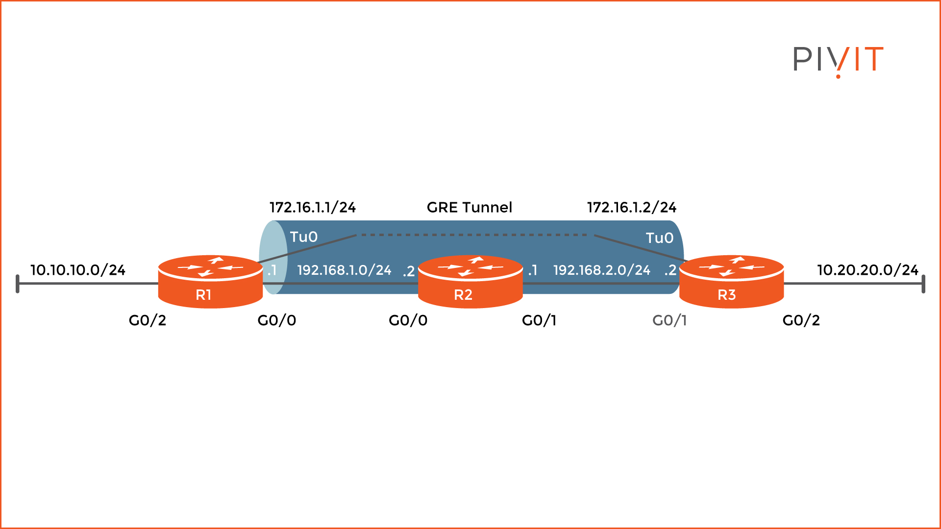
The image below shows the topology that will be used to configure a GRE tunnel between routers R1 and R3. Let’s focus only on the tunnel configuration and assume that all physical interfaces on the routers are already configured with the appropriate IP addresses, as well as other routing commands for proper communication within the topology.
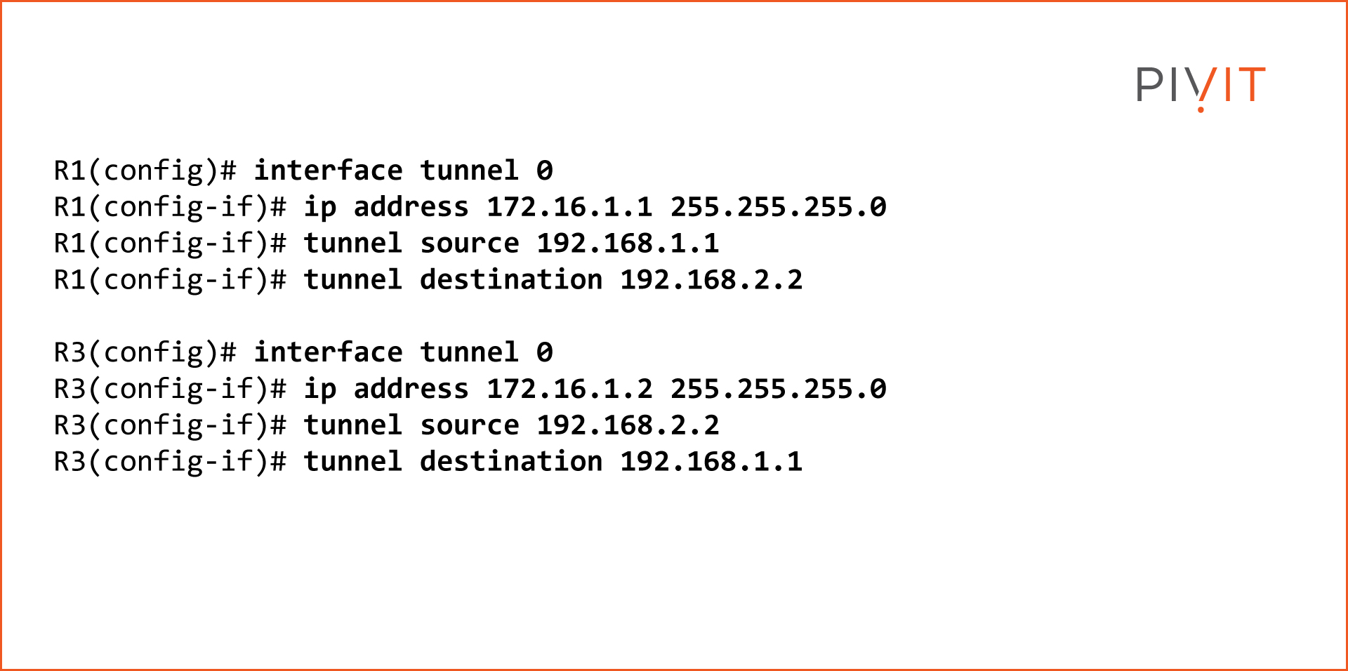
Step 1 - Configure the Tunnel
First, create the tunnel interface on R1, which in this case will be tunnel 0, and assign an IP address, in our example 172.16.1.1. Then, define the source and the destination of the tunnel. As the source, specify the IP address assigned on the GigabitEthernet0/0 interface or 192.168.1.1.
As the destination, use the IP address assigned on the GigabitEthernet0/1 on R3 or 192.168.2.2. The configuration on R3 is more or less the same, but with opposite parameters.
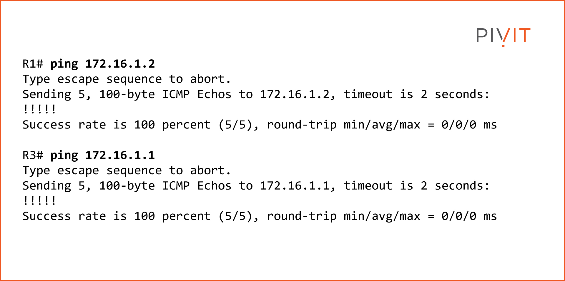
Step 2 - Verify It Is Working
Now that the GRE tunnel is configured, verify that it is working. To accomplish that, ping the IP addresses assigned to the tunnel interfaces.
Step 3 - View Routing Tables
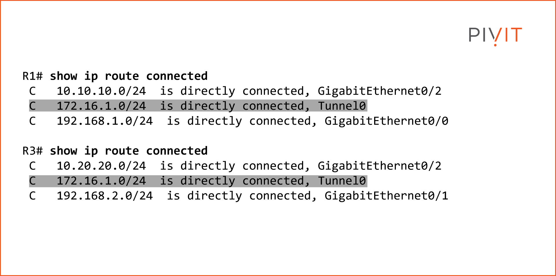
Since the GRE tunnel is operational and both IP sides can ping each other, take a look at the routing tables of both routers and confirm that the 172.16.1.0 network is directly connected to them.
Step 4 - Enable OSPF and Confirm Operation
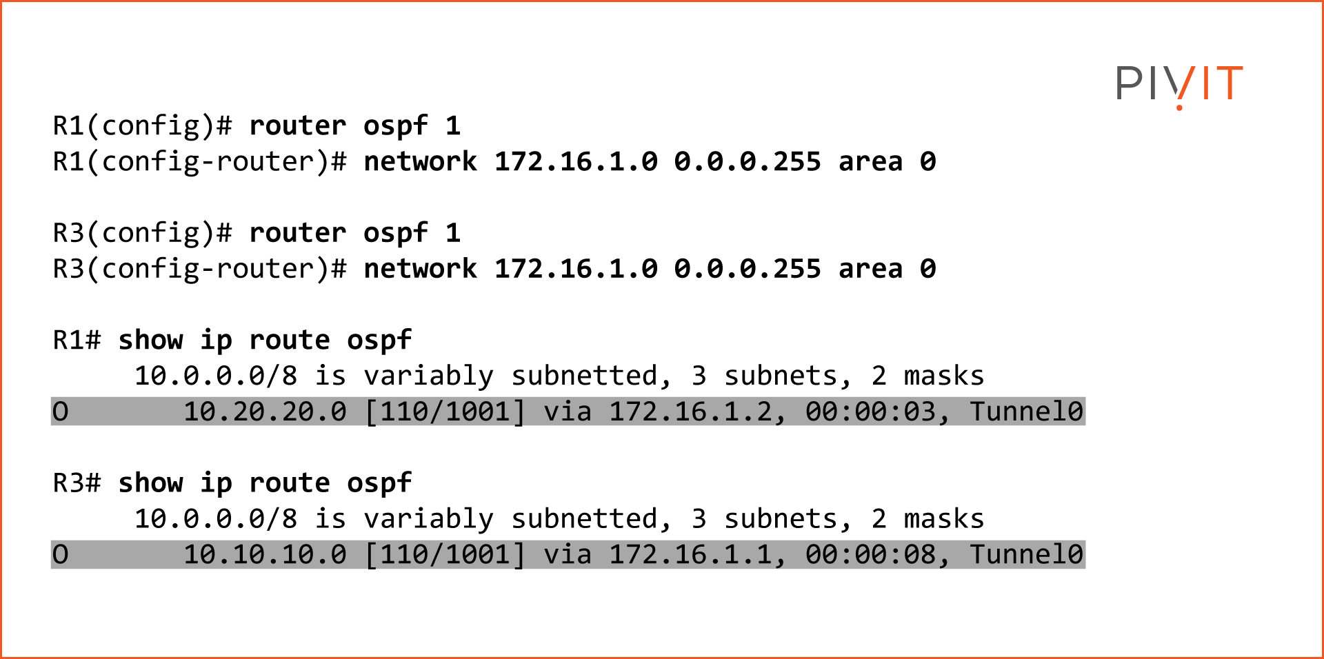
Enable OSPF on routers R1 and R3 to get a better idea of how packets are sent across the GRE tunnel. As confirmation, check the routing table of each router and verify that the tunnel interfaces are used as exit interfaces to reach those networks.
For simplicity, assume that OSPF is already configured and so we enable it only on the tunnel interfaces. The commands below show that GRE has been configured successfully by exchanging network information through OSPF packets.
For more information about OSPF, take a look at our article entitled An Engineer's Guide to Configuring OSPF Authentication.
Are You Going To Implement a GRE Tunnel?
To summarize, the GRE tunnel is a simple method for establishing a point-to-point virtual link between two L3 devices inside the local network or across the internet that need to exchange data directly with each other. Because many vendors support it, interoperability is not usually a problem and it can easily be implemented.
On the other hand, do not forget that GRE is not a replacement for VPNs. It might support different types of data to be sent across the tunnel, but it is not secure and should not be used across the internet without additional protection such as IPsec.
Also, keep in mind that GRE may be CPU intensive on some platforms and can exceed the MTU because of the additional header, which might lead to fragmentation if proper modifications are not in place.
Protect Your Routing Hardware
PivIT's OneCall service is the only holistic solution you will need for your router and other IT asset maintenance needs that can deliver each and every time on both a local and a global scale. See our extensive global coverage here. When it comes to protecting your mission-critical assets and even your legacy systems, OneCall has you covered.