Switches play a crucial role in each network regardless of their size. They’re a fundamental building block for any network, connecting devices. Besides the support they provide for end devices to gain network access, they are also responsible for exchanging frames and performing filtering actions based on IP or MAC addresses.
Based on the switching mechanism, packets are processed in a certain way and always delivered to the final destination. However, not all mechanisms are equally productive and user-friendly on the switch hardware resources.
Cisco switches support a special wire-speed mechanism that processes packets at high speeds. Cisco Express Forwarding builds Layer 2 and Layer 3 tables in the hardware and uses that information to forward packets as fast as possible in the most efficient way.

In this article, we will provide the following:
- An overview of Layer 2 switching.
- An explanation of the purpose of CAM and TCAM tables.
- An outline of the role of control and data plane.
- An exploration of Cisco switching mechanisms.
- A list of the benefits of using CEF.
Not what you were looking for today? View some of our popular articles:
- The Complete Solutions Guide to a Redundant Switched Topology – Pt. 1
- A Complete Guide To Improving Redundancy with EtherChannel Technology
- Interior Routing Protocols Comparison: RIP vs EIGRP vs OSPF vs IS-IS
Layer 2 Switching Overview
Typically, when people discuss switches, they mean Layer 2 switches. The main goal of a Layer 2 switch is to receive and send frames on the interfaces. This process is possible with the help of the MAC address table, also known as the Content-Addressable Memory (CAM) table.
The approach that switches use to forward frames and populate the MAC address table is quite simple. When a switch receives a frame, it first checks the source MAC address inside the frame.
If the MAC address is not in the MAC address table already, the switch creates a mapping and records several parameters, such as the MAC address, the switch port where the frame was received, and the VLAN to which the interface belongs.
Based on this data, the switch forwards the frames afterward. It checks the MAC address table to find the destination MAC address included in the received frame and, according to the matched entry, uses the corresponding exit interface.
The destination MAC address in the frame is not always known to the switch.
In such a case, the switch forwards the frame through all ports in the VLAN except the interface on which the frame was received.
This behavior is known as unknown unicast flooding. The same happens when the destination MAC address in the frame is broadcast or a multicast MAC address.
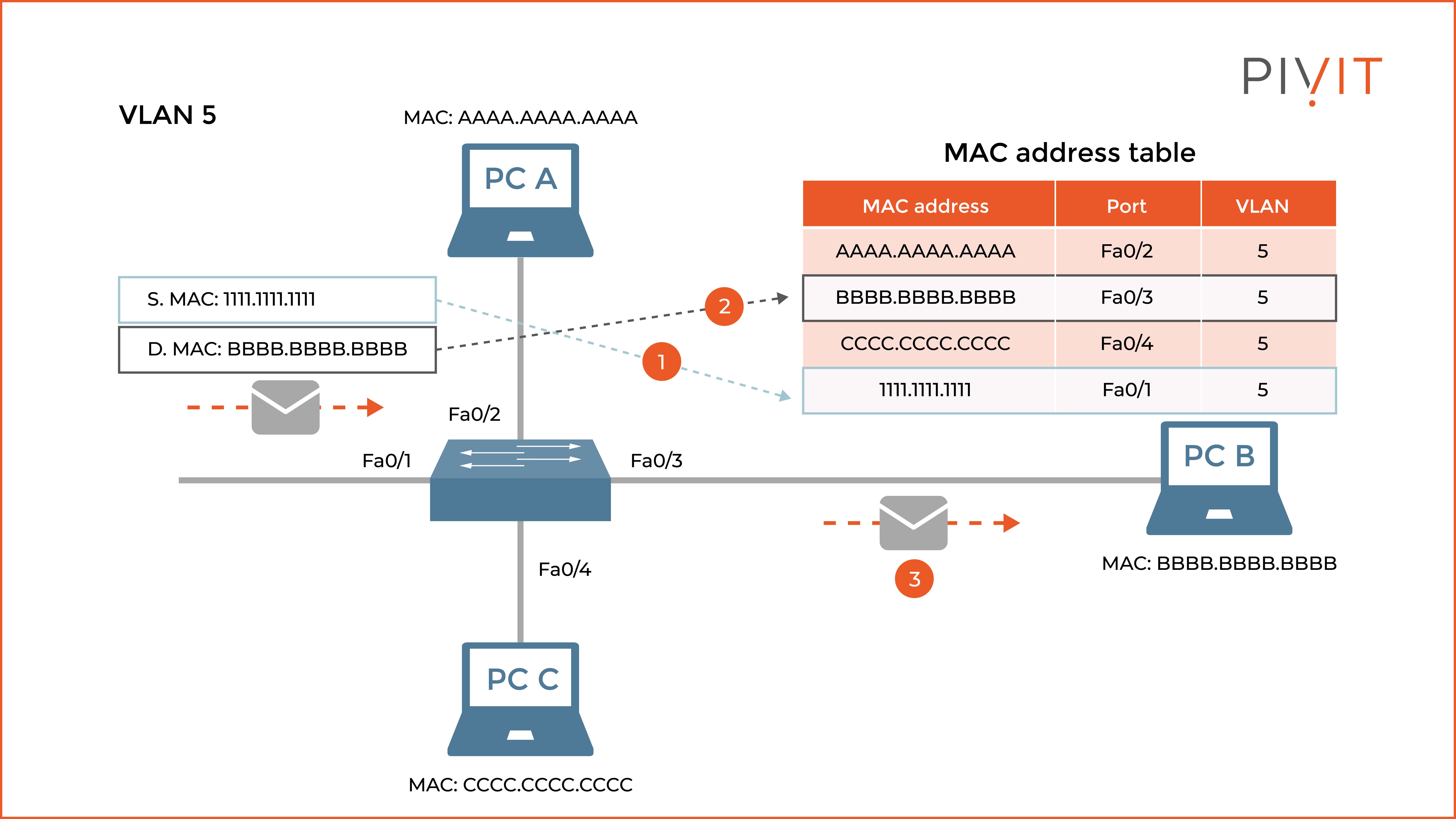
As you can see in the image above, the switch receives a frame that should be sent to PC B. If the source MAC address from the frame is unknown at that point, the switch saves it in the MAC address table. Then, based on the destination MAC address, finds the appropriate entry in the table and uses Fa0/3 as an exit interface to send the frame to PC B.
The total number of MAC addresses that can be stored in the MAC address table depends on the switch model. Regardless, when the MAC address table is full, the switch stops acting like a switch, and its behavior becomes like a hub.
It means that, from that point on, the switch starts flooding each frame, regardless of the type of destination MAC address included in the frame. Therefore, it is essential for the MAC address table never to reach its limit.
The entries in the MAC address table are kept until there are active communications. However, after five minutes of inactivity (default timeout), the mappings are discarded from the MAC address table.
Keep in mind that frames are always rewritten on the output interface of a router or a Layer 3 switch when a packet travels from one network to another.
This means that the existing source and destination MAC addresses of the received frame are replaced with new ones and then sent to the next-hop MAC address. The source and destination IP addresses in the Layer 3 header never change.
Maintaining CAM and TCAM Tables
Although the switching is based on the content from the MAC address table, sometimes additional features influence the processing decision, such as ACLs and QoS rules. While ACLs identify a frame according to its MAC addresses, the QoS can prioritize and rate-limit certain traffic. However, the key point is the location where this information is stored.
ASIC hardware allows Cisco switches to forward frames and packets at wire speeds. This supports Layer 2 and Layer 3 parameters, such as learned MAC addresses and defined ACLs and QoS rules to be cached into the hardware itself, also known as CAM and TCAM tables.
Cisco switches maintain CAM and TCAM tables. They provide speedy processing of data. The CAM table is the main table for making Layer 2 forwarding decisions, where everything is based on the MAC addresses stored. In other words, the CAM table is the same as the MAC address table.
While CAM is used for Layer 2 switching, the TCAM table is for Layer 3 switching. The TCAM table stores ACLs and QoS rules, as well as other information needed for the upper-layer processing.
For each ACL, QoS, or other feature, there is a separate TCAM table on the switch. Multiple TCAM tables allow the switch to perform different checks in parallel without suffering performance degradation.
The Purpose of Control and Data Plane
A network device utilizes a distributed architecture in which two separate contexts are identified by their functionality planes, each with a different objective and goal. These two main planes are:
- Control plane: This plane allows the device to build all essential control structures, such as the MAC address table and the routing table needed by the data plane operations. In other words, the control plane is responsible for learning information required to process incoming frames and packets.
- Data plane: The main task of this plane is to provide data switching and data routing functionalities using the information learned in the control plane. Besides forwarding network traffic, the data plane also applies additional services, such as QoS, security services, or optimization. The switch uses the MAC address table learned in the control plane when forwarding frames.
Keep in mind that except for the control and data plane, devices have a management plane as well. The main functionality of the management plane is to provide devices with all necessary functions so that administrators can configure and monitor them.
Using Process Switching
When a Layer 3 device, such as a router, uses process switching, it strips the Layer 2 header for each received frame. It then uses the routing table to find the exit interface for the destination IP address included in the Layer 3 header.
Before the frame is sent out from the outgoing interface, a new Layer 2 header is appended to the frame, and the Cyclic Redundancy Check (CRC) is redone because of the new information.
The key point in process switching is that the CPU of the device examines each frame.
When the CPU performs the processing, all forwarding decisions are made in software, resulting in the process switching being the slowest switching mechanism.
Moreover, process switching is the most CPU-intensive method as well. When used, it heavily decreases the device's performance and should only be used as a last resort when other better switching mechanisms cannot be used.
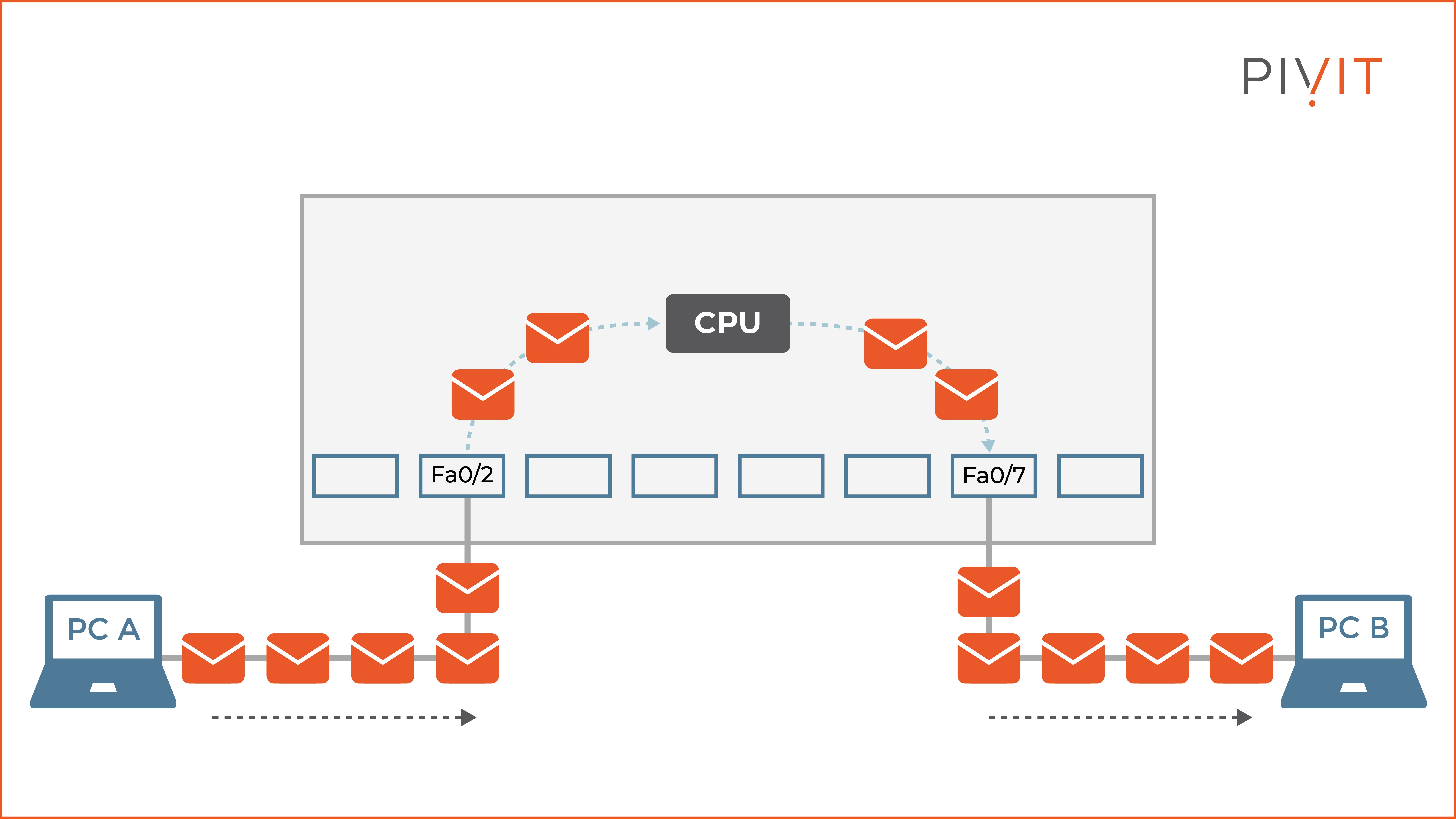
As you can see in the image above, the router receives incoming frames from PC A on interface Fa0/2, and each one gets processed by the CPU because of the process switching method used. After the frames are processed, they are forwarded out of interface Fa0/7 connecting to PC B.

Understanding the Fast Switching Method
Fast switching is a faster switching mechanism than process switching because forwarding decisions are cached in hardware and used for the rest of the traffic flow for the same session between the source and the destination hosts. However, the first packet is always processed by the CPU.
The fast switching method relies on a fast-switching cache where all essential parameters for the session flow are stored. However, the fast-switching cache is empty by default and starts adding information once frames are received on the interfaces.
When the first frame arrives on the Layer 3 device, it tries to find the destination IP address in the fast-switching cache. Because it is not there, process switching is performed, and the CPU processes the frame.
At the same time, the router creates an entry in the fast-switching cache, which allows all subsequent frames for the same traffic flow to be fast-switched. As a result, the device rewrites the frames extremely fast because of the cached data and sends them through the outgoing interface.
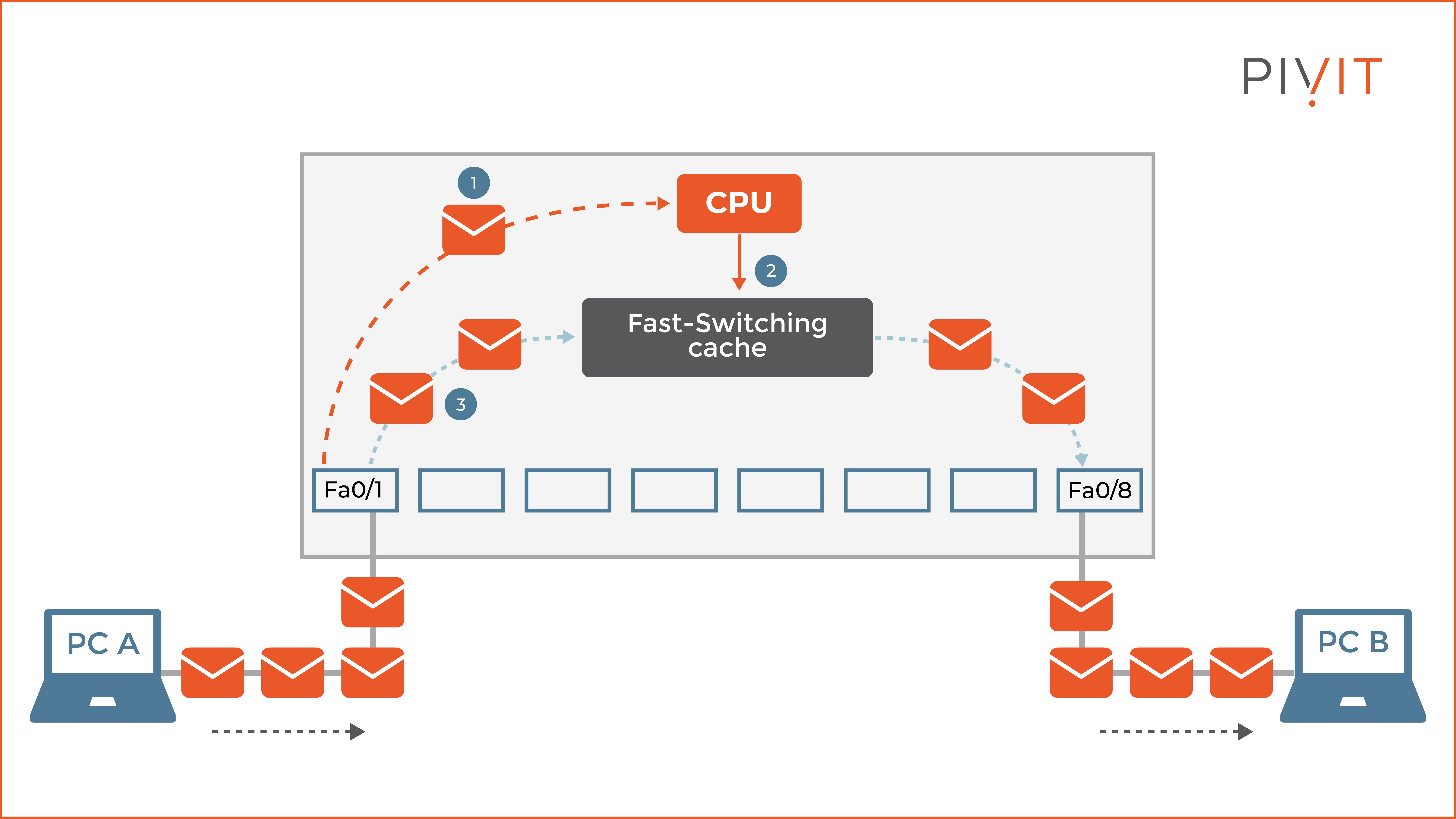
As you can see in the image above, the router receives incoming frames from PC A on interface Fa0/1 that should be sent to PC B. The first frame gets processed by the CPU because the destination IP address is not available in the fast-switching cache. Once the entry is created in the fast-switching cache, the rest of the frames are fast switched and sent out on interface Fa0/8 to PC B.
All About Cisco Express Forwarding
Cisco Express Forwarding (CEF) is less CPU intensive than fast switching and process switching mechanisms and is the default switching mode on Cisco devices. When CEF is enabled on a device, it uses the information from the tables built by the CPU, such as the Layer 3 routing table and Layer 2 ARP table, to build corresponding hardware-based tables.
This means that CEF caches all the information from the ARP table into an adjacency table and all information from the routing table into a Forwarding Information Base (FIB) table. From that point, the router uses only the adjacency and FIB tables.
This allows the router to make hardware-based forwarding decisions for all the frames in a data flow, including the first frame.
The whole concept of the CEF switching mechanism is as follows.
All prefixes from the routing table are stored in the TCAM table, from the most specific to the least specific entry. When a FIB lookup is performed, it is based on the destination IP addresses, matching the entries within the TCAM table.
On the other hand, the adjacency table contains Layer 2 header rewrite information for each next hop included in the FIB table, ready to be immediately applied on the frame before being sent out on the exit interface.
This approach significantly speeds up the process of rewriting frames. When a network change happens, the routing and ARP tables update themselves, and the same change also reflects on the adjacency and FIB tables.
The device's control plane is responsible for building the FIB and adjacency tables in the software. On the other hand, the data plane is responsible for using the information from these two tables and forwarding the data traffic in the hardware. Because of this concept, the device achieves higher data throughput with fewer processing resources spent.
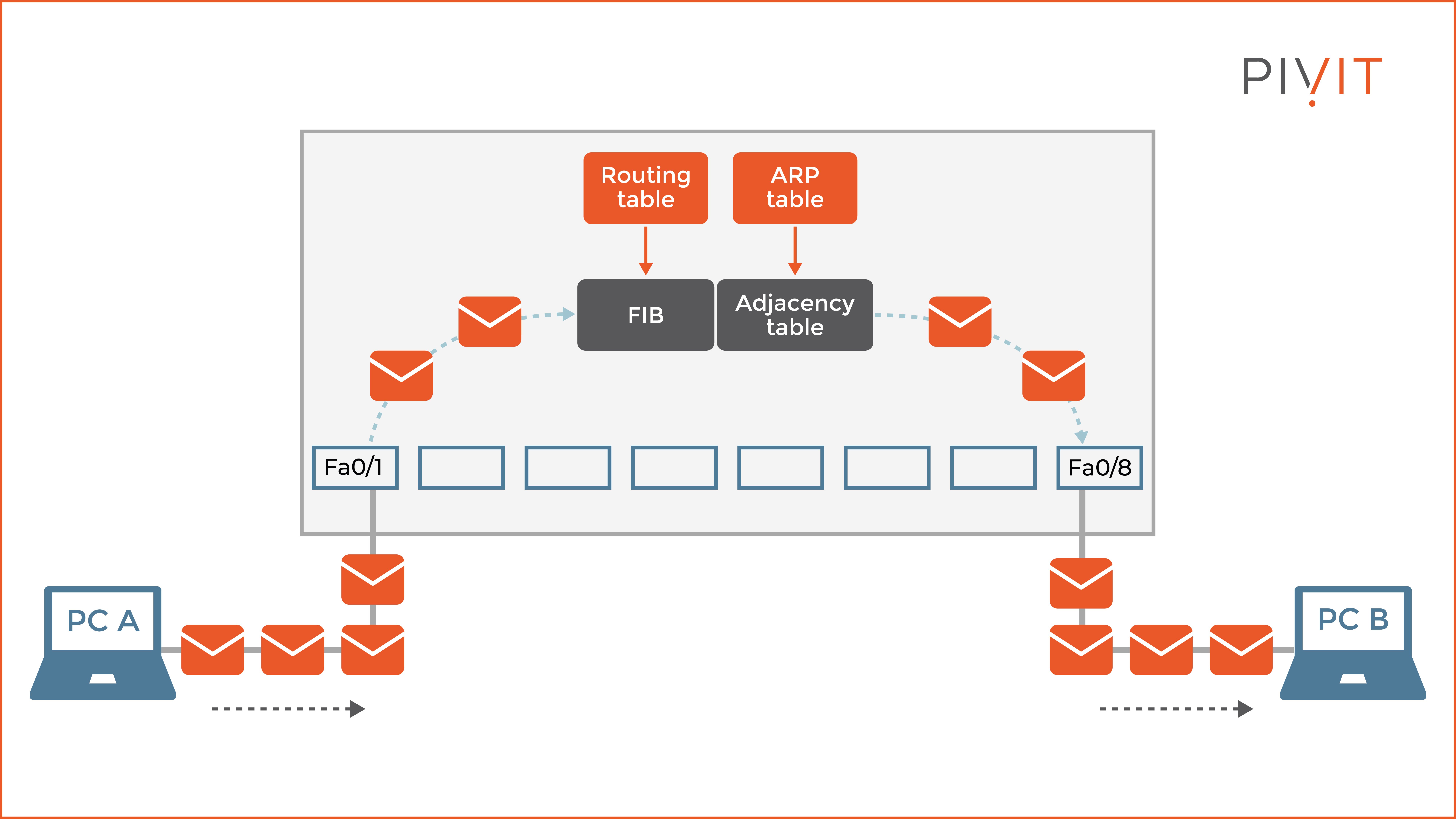
As you can see in the image above, the router builds a FIB table based on the information available in the routing table and an adjacency table based on the information in the ARP table. This allows the router to perform hardware processing on all frames, including the first one, simply by using the cached information.
As a result, the traffic flow between PC A and PC B is less intensive on the device resources, and the data is delivered to the destination in less time.
Although CEF is the fastest switching mode, it cannot always be used for switching frames. There are some features on the network devices that are simply not compatible with the CEF method.
As a result, when data traffic cannot be processed in the hardware, the CPU must switch software. Sometimes CEF can even degrade performance, such as when using load-balanced Layer 3 paths in the network topology.
CEF, the King of Switching Mechanisms
Although each switching mechanism used on the Cisco devices will process the data and forward it through the exit interface toward the destination IP, not all equally spend the device resources.
CEF, by far, is the most efficient switching method, which is why it is enabled by default. It’s always recommended to use CEF unless specific data traffic does not support this switching method, so the device must switch over to fast switching the frames.
Switches are crucial in each network — and Cisco Express Forwarding is a top player in this arena. Keep this guide in tow the next time you need a crash course!
__________________
If you need a helping hand to configure your network, consider PivIT's EXTEND SmartHands offering to gain access to engineers around the globe to locally access your infrastructure without ever leaving your desk. But don't take our word for it, here's what one of our clients had to say:
"Great response time by the PivIT team, they came through in a pinch and we really appreciate it." - Jarrod S. (Director of Infrastructure)

__________________