%20tech%20corner%20image%20(1).png)
In every network, data packets are exchanged among hosts through numerous networking devices along the traffic path, such as switches, routers, and firewalls among other devices, so you can comfortably perform your daily tasks.
Although the traffic transfer happens instantly, the host-to-host delivery operation, either in the same network or between different networks, is not a simple task and a series of processes are included along the way.
For that reason, a default gateway must be configured on most of your devices, if not all, and must use the Address Resolution Protocol (ARP), so that devices can properly encapsulate the data before sending it to the destination.
In this two-part article series, we will explore the packet delivery process in more detail and find out what happens during host-to-host communication.
Let PivIT handle your router setups with EXTEND, which serves as a seamless and confidential extension of your IT teams. Consider us your boots on the ground working to cost-effectively extend your reach and complete your projects.

Host-to-Host Packet Delivery Step-by-Step
Let us look at a simple example in which data is sent from one device to another to understand the steps involved in host-to-host packet delivery.
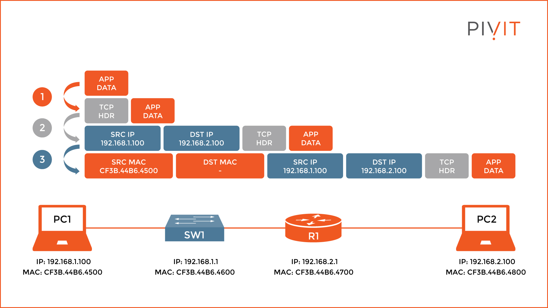
As you can see from the image above, the topology is quite simple and consists of only two computers, a switch, and a router. On the left of R1, the 192.168.1.0/24 network is used, while on the right is the 192.168.2.0/24 network.
The IP and MAC addresses for each interface of the devices are also known, except for the switch because it is irrelevant for our host-to-host delivery example.
If you require a switch for your network, but you are not sure which is best, view some of the following posts:
- Comparing the Cisco 3560, 3850, and 9300 Switches
- Comparing Market Leaders: Cisco and Arista Switches
- Deep Dive Comparison: Cisco's Catalyst 6500 & 6800 Switches
- Head-To-Head With the Cisco Catalyst 4500 vs. 9400 Chassis Switches
For the example to make more sense, let’s add some story behind it. Let’s assume that PC1 needs to remotely connect to PC2, which resides in a different network and uses Telnet as a communication method.
So, what will happen when the user behind PC1 enters the Telnet command to connect to the IP address of PC2? Well, most likely the user will be asked for credentials, which means PC1 and PC2 communicated to each other, but what happened in between is what this article is all about.
Step 1 - TCP Protocol and Layer 3 Header
Firstly, on PC1, the Telnet application sends the data, to which an additional header is appended and indicates a TCP session is being used. The reason for using a TCP header is that Telnet is using the TCP protocol for establishing connections.
When this task is finished, the data and the TCP header continue with the encapsulation process, and a Layer 3 header is appended to the previous parameters. This header contains the source and destination IP addresses of the communicating devices, PC1 and PC2 in our case, among many other parameters included.
Therefore, the source IP is the IP address of PC1 (192.168.1.100), and the destination IP is the IP address of PC2 (192.168.2.100).
Step 2 - Layer 2 Header and ARP Protocol
The next step is appending the Layer 2 header, which includes the MAC addresses of PC1 and PC2. However, before this, PC1 needs to find out if the destination host is in the same network or belongs to a different one.
The reason for that is quite simple. The computer is not capable of routing and so everything must go through a Layer 3 device, such as a router, that will serve as a default gateway for sending data in different networks.
To learn more about this process, be sure to check out our article entitled Exploring the Functions of Routing and the Routing Table.
Because PC1 and PC2 belong to different networks, PC1 must send the data to R1 first, which will forward it to PC2 afterward. Therefore, PC1 needs the MAC address of R1, instead of PC2.
But does it have it? If yes, the encapsulation process continues, however, if the MAC address of R1 is not known, the ARP protocol is used.
Get help choosing the best router for your network by speaking with our specialists.

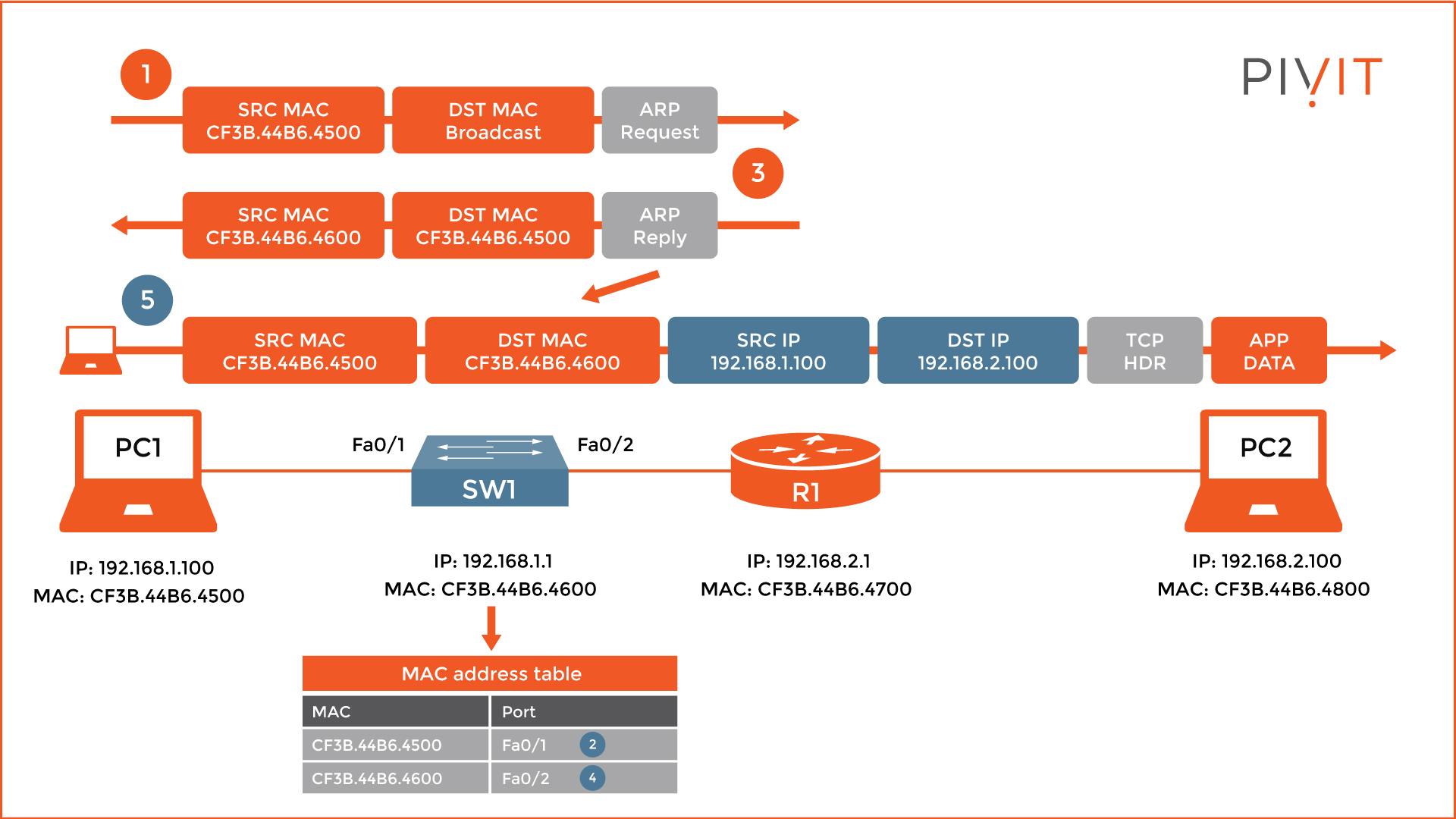
For that reason, as you see from the image above, PC1 sends an ARP request message, where it uses its own MAC address as a source, while the destination MAC is a broadcast.
When R1 receives the ARP request message, it learns the MAC address of PC1, maps it to the corresponding IP address inside the local ARP table, and replies with an ARP reply message.
Upon receipt, PC1 learns the MAC address of R1 and writes that information in its own ARP table. Now, PC1 has the missing parameter and can finish the encapsulation process.
It is very important to note that the ARP messages do not play any special role on the switch, except to learn the MAC addresses of PC1 and R1 and store them inside the MAC address table for later use.
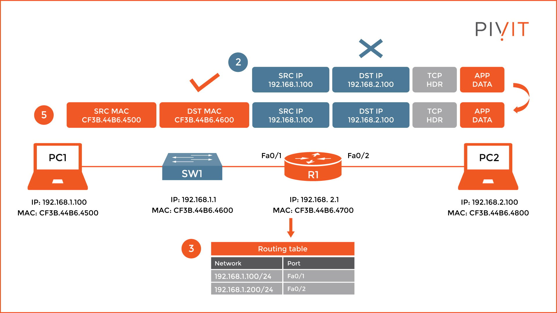
When R1 receives the packet, it recognizes the destination MAC address in the Layer 2 header and starts a decapsulation process. However, this process stops when it finds out that the destination IP address in the Layer 3 header is not locally used.
Because the packet must be forwarded, it checks the destination table and finds out that the FastEthernet0/2 should be used as an exit interface to reach the destination network, where PC2 belongs.
Step 3 - Repeat
So, what happens next? Well, the same process repeats. As you can see from the image below, R1 needs the MAC address of PC2, so it can add a new Layer 2 header and finish the encapsulation process.
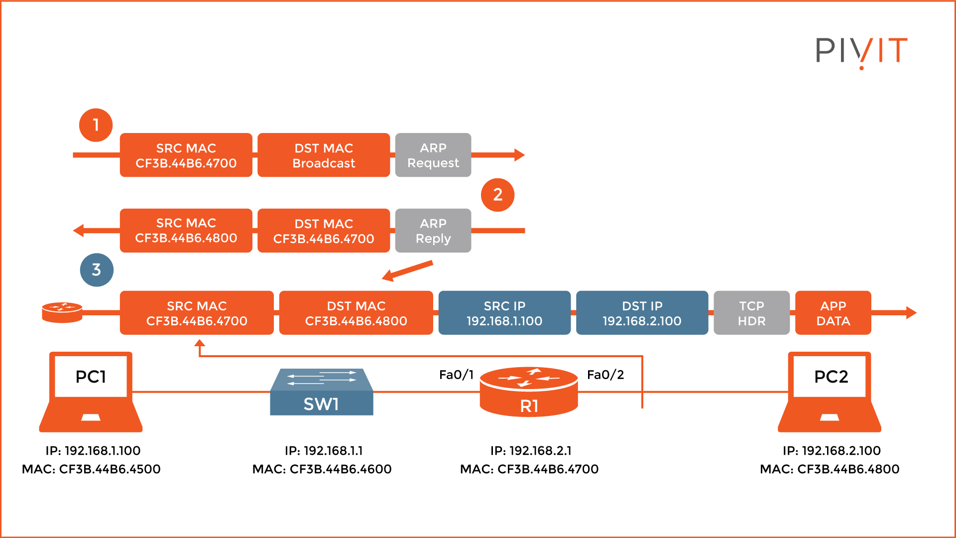
If the MAC address is not known, R1 sends an ARP request message, and upon receipt, PC2 replies with an ARP reply message. After learning the MAC address of PC2, R1 appends the Layer 2 header to the rest of the packet parameters, using its own MAC address as a source, and the MAC address of PC2 as a destination. Now the packet can finally be sent to PC2, which triggers PC2 to reply with a prompt for entering Telnet credentials.
Troubleshoot Your Network Like a Pro
We’ve shown that when a user behind PC1 starts a Telnet session to PC2, they instantly get an authentication request. However, a series of processes are executed during that time.
Knowing the steps involved can help you to understand the whole encapsulation and decapsulation process, which can come in handy when troubleshooting services in your network.
Don't let unreasonable lead times stop you from getting the routers you need. PivIT gives you the freedom to choose from an extensive network of OEM partnerships, maximize your budget, and create a strategy to keep your network scalable.