.png)
The Hot Standby Router Protocol (HSRP) is a Cisco proprietary redundancy protocol. It allows several Layer 3 switches or routers to work together in an HSRP group and appear as a single virtual device to endpoints. Because of this approach, endpoints always have a functional default gateway, regardless of which physical router or switch processes the data traffic because of the active role.
In this Part 2 article, we will provide an overview of HSRP, find out how it can be implemented, and get details on some of the additional features it supports. Miss Part 1? Don't worry, view it here.
____________
Hardware Options
At PivIT, we bring options to the table that your traditional VAR won't, whether it is OEM options, financing options, maintenance options, and more. Click below to browse for a router and get started bringing options to your network!

____________
Implementing HSRP
To implement HSRP, you need to add two or more routers or L3 switches in an HSRP group, where only one operates as active and one is in standby mode. The standby device monitors the active device and takes over the active role when the active device fails. Both devices share the same virtual IP address and MAC address. However, only the active device is responsible for the virtual addresses.
.jpg?width=1920&name=1%20(6).jpg)
Let’s look at the image above to understand the implementation process. In this use case, we want to add two routers (R1 and R2) in an HSRP group 1, where R1 will serve the active role, process all endpoint data, and reply to ARP request messages. At the same time, R2 will be the standby device and monitor the status of R1.
Before we get there, you should know that in HSRP, each role has different functionalities. The active device, such as R1, is responsible for replying to ARP requests, forwarding all data packets, sending hello messages to the standby device in the group, and using the virtual IP address.
On the hand, the standby device (R2 in our example) has a lesser role, and only sends hello messages, listens for hello messages from the active device, and assumes the active role if the active device (R1) fails.
Configuration Example
The configuration process is quite simple and consists of only several commands for basic HSRP functionality. In this example, we will focus only on configuring R1, but keep in mind that the configuration of R2 would be identical.
.jpg?width=1920&name=2%20(5).jpg)
The HSRP configuration is entered inside the interface mode that connects to the other device in the HSRP group. In our case, this is interface Fa0/1 on R1 that connects (through the switches) to interface Fa0/1 on R2. The IP address used on Fa0/1 is 192.168.1.1, the virtual IP address is 192.168.1.254, and the router belongs to Group 1.
Although the group numbers are locally significant, it is recommended (for easier management) to use the same number on the devices included in the HSRP group.
.jpg?width=1920&name=3%20(4).jpg)
Because there are two versions of the HSRP protocol, an appropriate format for the virtual MAC address must be used. When using HSRP v1, only 256 groups are available, and the virtual MAC address uses the format 0000.0C07.ACXX, where XX represents the HSRP group number. HSRP v2 supports up to 4096 groups, and the MAC address has the 0000.0C9F.FXXX format, where XXX identifies the HSRP group.
The active and standby router selection is based on the higher priority number in the range between 0-255, where 100 is the default value. When the priority number is the same, the device with the highest IP address becomes the active device in the HSRP group.
When there are more than two devices in an HSRP group, one is active, one is standby, and the others listen and wait to become standby devices. To prioritize one device over another, you can change the priority numbers of the devices.
However, when failover happens, the standby device becomes active, which does not change unless this new active device fails. For the device with the highest priority always to be active in the group, you need to enable the pre-emption feature that is disabled by default. The following commands enable the pre-emption feature and increase the priority of R1 from the default value of 100 to 120.
.jpg?width=1920&name=4%20(2).jpg)
By default, the HSRP hello packets are sent every 3 seconds. The hold time is 10 seconds. Suppose the standby device does not receive a hello packet within 10 seconds from the active device. In that case, it will become the new active device.
To speed up the failover process, you can lower the timers (1-255 seconds) on the devices in the HSRP group. In extreme cases, you can even configure timers in milliseconds instead of seconds. However, ensure the hold time is at least three times the hello time.
For example, if you want the hello packets to be sent every 200 milliseconds and the hold time to be 750 milliseconds, the configuration command would look like this:
R1(config-if)# standby 1 timers msec 200 msec 750
To verify the HSRP Router configuration on R1, you can use the “show standby” command.
.jpg?width=1920&name=5%20(2).jpg)
If you're having issues implementing HSRP, view our article on the common issues network engineers face with HSRP and ways to troubleshoot those problems. Get it here.
HSRP Advanced Features
The standby device takes over the active role only when the active device fails to send hello messages during the defined hold time interval. By default, the HSRP active device loses its status only when the HSRP-enabled interface fails or when the HSRP-enabled device fails.
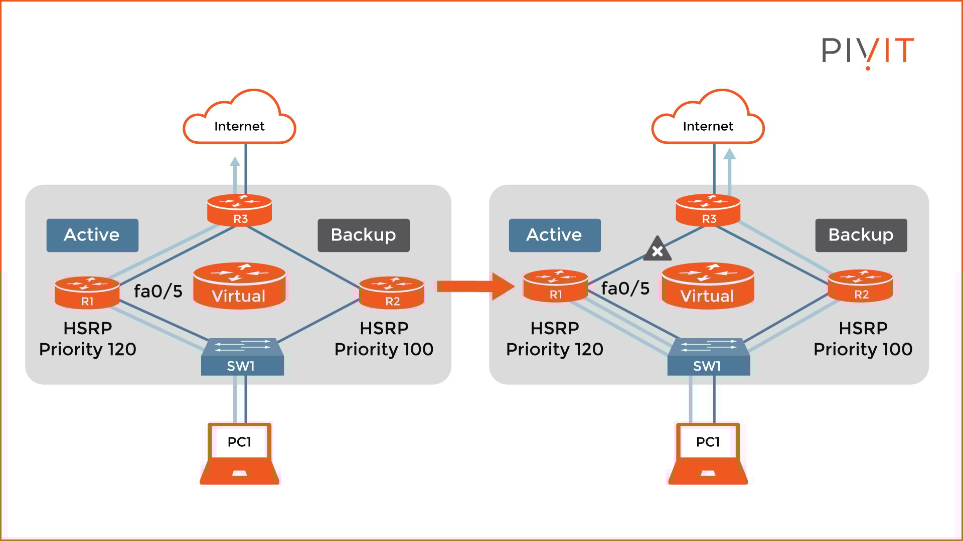
However, this is not always enough to failover properly. As you can see in the image above, when the uplink (Fa0/5) on R1 fails, the active and standby roles on the routers do not change because the HSRP-enabled interfaces on the routers are still active, and hello messages continue to flow in both directions.
As a result, when the packet is sent from PC1 toward the internet, it first goes to R1. Then, because of the routing protocols, the route changes and goes back to R2, R3, and finally exits the network. Even though the packet still gets to the destination, there is suboptimal routing, which should always be avoided.
Because of situations like this, there are other mechanisms to trigger HSRP-active election, such as HSRP interface tracking and object tracking. So, let’s take a look at the examples for both mechanisms.
HSRP Interface Tracking
You have to enable the interface tracking option on a non-HSRP-enabled interface on the device, which will start monitoring the status of that interface. Suppose the line protocol goes down.
In that case, the HSRP priority of the device gets decreased by the value specified (the default is 10), which allows the standby device with a higher priority to become the new active router. Do not forget that this failover can only work when the pre-emption feature is enabled.
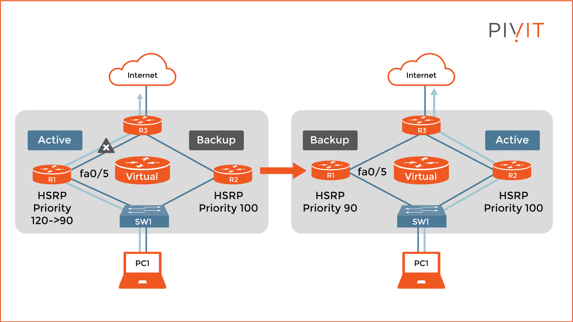
So, let’s look at the example in the image above. Now that the interface tracking is enabled for the Fa0/5 interface on R1, the priority changes from 120 to 90, which is lower than the standby router (100). Consequently, R2 takes over the active role.
The command to configure interface tracking is as follows:
R1(config-if)# standby 1 track FastEthernet0/5 30
HSRP Object Tracking
Although the interface tracking option functions perfectly, it only works for tracking interfaces on the HSRP-enabled devices in the group. However, if another uplink fails (on another router), this feature will not be able to perform a failover properly.
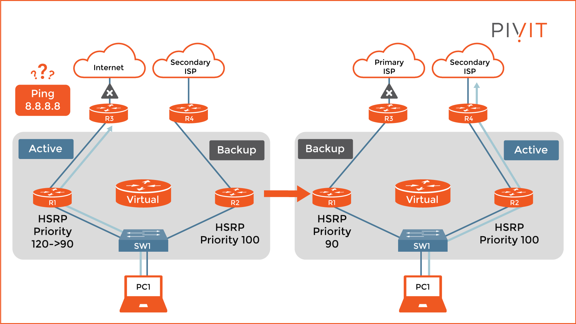
Let’s take a look at the image above. Both routers have uplinks to different service providers, providing a backup solution if the primary service provider fails. The problem is that we cannot track interfaces other than those on the HSRP-enabled routers. For that reason, we can use object tracking and define what should be tracked.
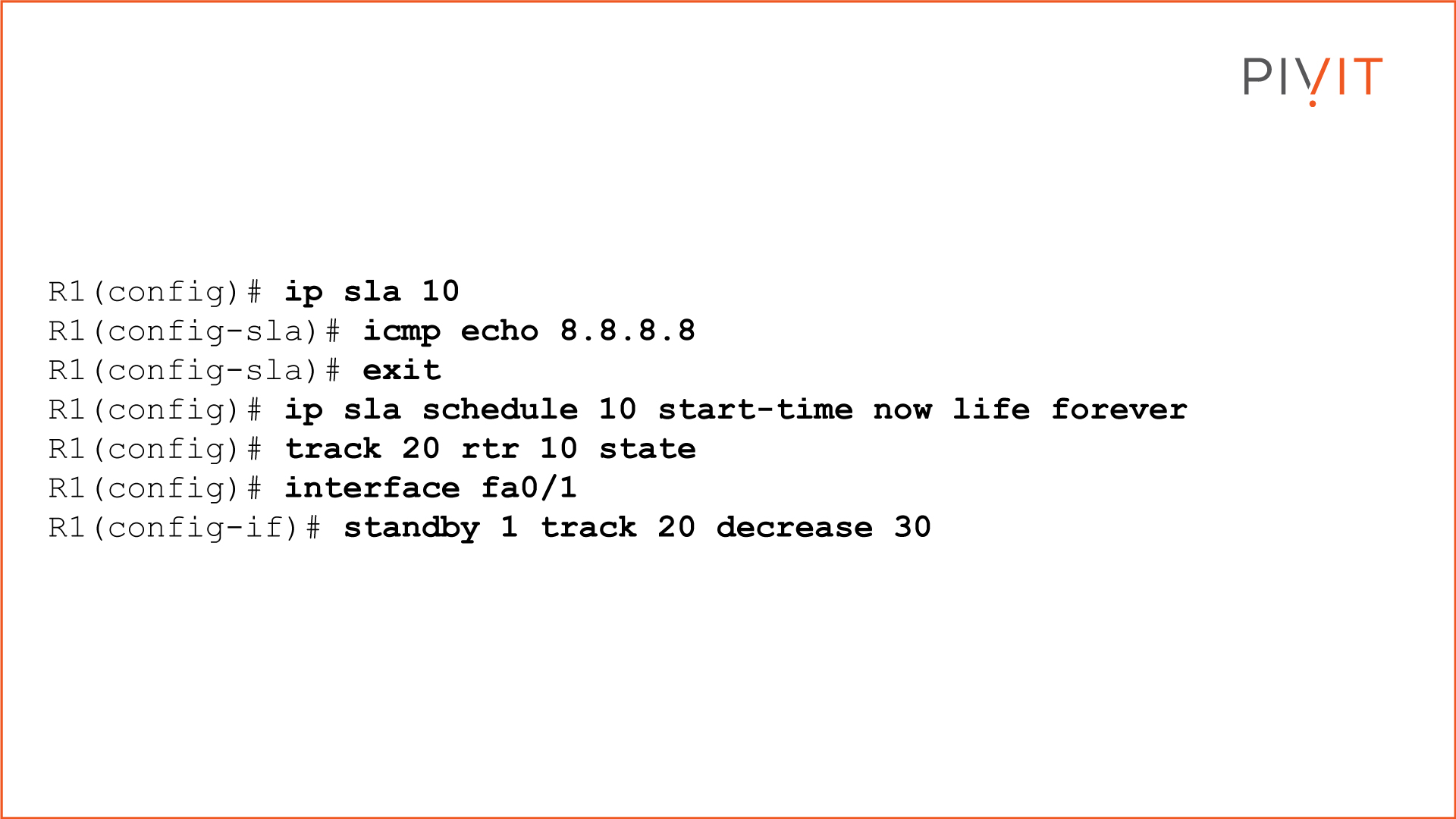
In this case, the best option is to track the link availability. We create an IP Service Level Agreement (SLA) process to ping a public IP address such as 8.8.8.8. Additionally, we need to track the state of this process. For that reason, we create an object that will decrease the priority by 30 when the process fails (unsuccessful ping) so that the standby router (R2) can take over the active role because of a higher priority (100 over 90).
The configuration commands for this use case are as follows:
Ensure You Fail-Safe
As you will have noticed from the examples we have discussed, configuring basic HSRP functionality brings many benefits to a network. However, sometimes it is just not enough to ensure proper failover between the devices in the HSRP group.
Based on your requirements, you have to implement some of the additional supported HSRP features to get the full benefits and make your network ready and prepared to react accordingly when unexpected failures happen.
If you don't have the resources to implement HSRP features, PivIT offers SmartHands as part of its EXTEND product. Gain access to engineers around the globe to help build your wired and wireless networks without ever leaving your desk when you are tackling staff shortages, complex environments, office relocations, or emergency situations.

View some of our past articles on various routing topics:
- The Essential Guide To Protect Against ARP Spoofing Attacks
- Essentials of Packet Delivery Process (Default Gateway and ARP) - Pt. 1
- Learn the Packet Delivery Process (Host-to-Host Communication) - Pt. 2
- Exploring Routing Functions and the Purpose of the Routing Table