-1.png)
For everyday network operations and proper exchange of data throughout the enterprise environment, routing functionality must be implemented on Layer 3 devices. This functionality is usually performed on routers, although it can also be provided by other devices such as firewalls and Layer 3 switches.
The main goal of routing is for the routers to be able to forward traffic to different parts of the networks when required. When a router receives a packet, it always uses the best route to forward the packet to the destination IP.
For that reason, determining the best route must be performed before the packet is received. The process involves an evaluation of all available paths to the same destination network and selecting the optimal one.
Therefore, routers must know the networks within the premises before the selection starts. The learning process of the networks can be done in multiple ways such as using static or dynamic routing. However, only the best routes to each network are used in the routing table.
In this article, we provide an overview of the routing functionality, the routing table, and its purpose, as well as the types of routes and the forwarding process by using the routing information.
The Importance of Using a Router
Just like the networks cannot function without switches, the same applies to routers. Since every single network has one or more of these Layer 2 and Layer 3 devices, knowing the purpose of each and the difference between them is quite important to understand the impact of the routers in a network.
Switches exchange data frames only between segments to enable communication within a single network. This means that communication between the endpoints in the same VLAN or subnet will function without any limitations whatsoever.
However, the problem arises when endpoints in one network need to communicate with endpoints in another network. Because the switch is a Layer 2 device, the routing capability is not supported.
For that reason, you need a router. A router is a networking device that forwards packets between different networks. Each interface on the router belongs to a different network and, therefore, internetwork communication between the networks is supported by default.
As a result, directly connected networks are always available in the routing table, and the router can forward data toward endpoints or other networking devices that belong there.
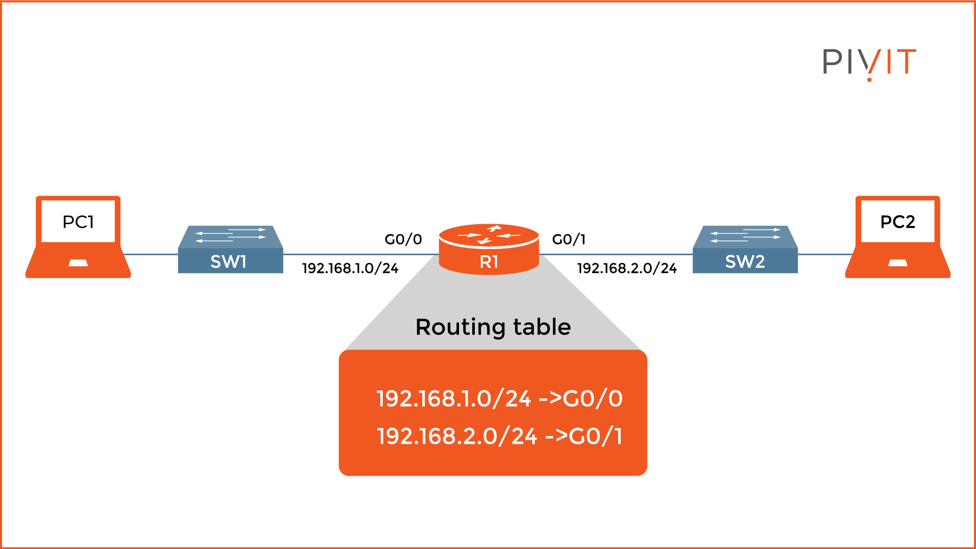
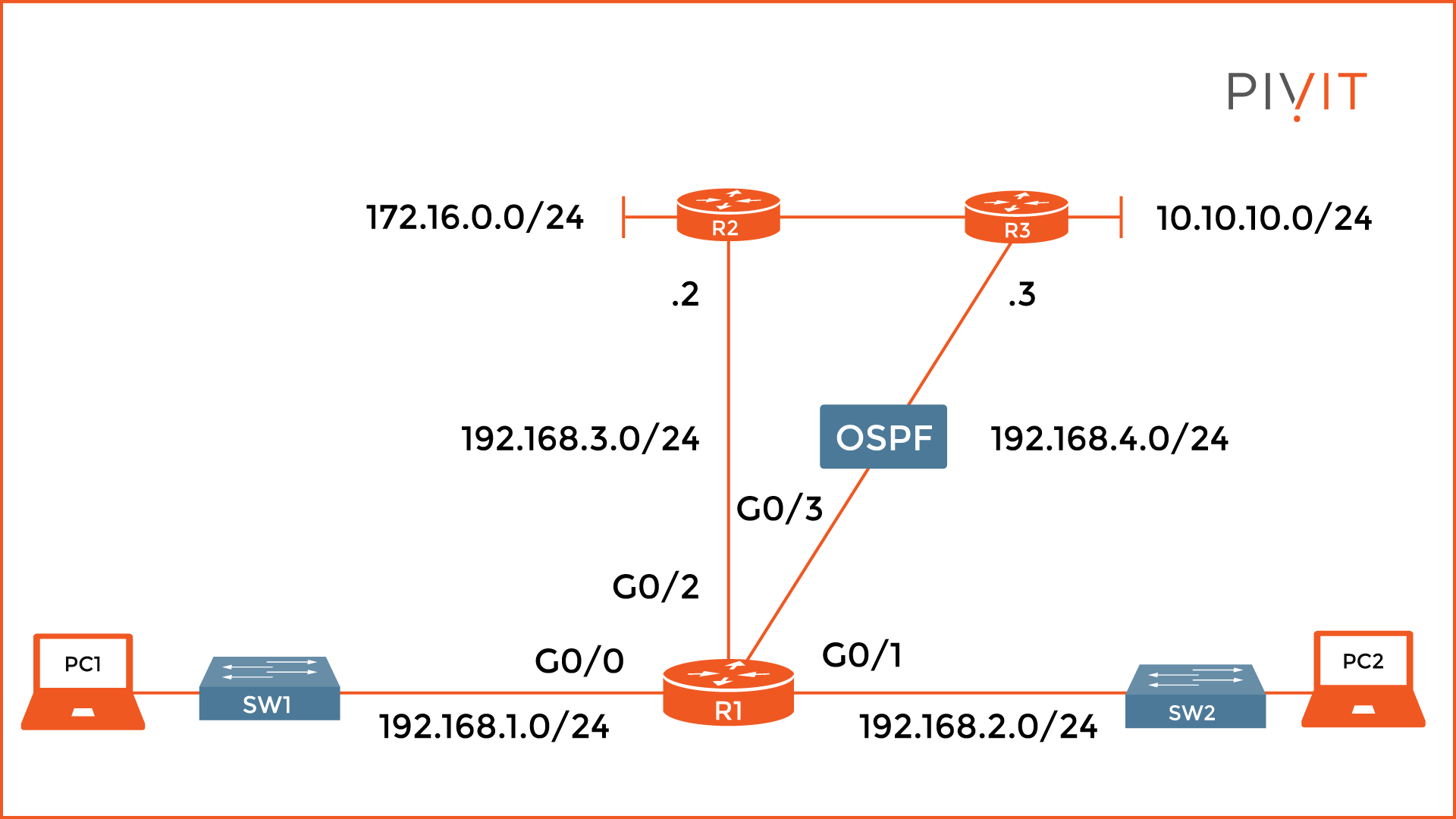
In the image above, you can see that the router has two directly connected networks, 192.168.1.0/24 toward SW1 and 192.168.2.0/24 toward SW2. As a result, PC1 and PC2 can communicate with each other.
Router Functions
Routers are essential for proper traffic forwarding between the networks within enterprise premises. To achieve this, they perform two important functions, namely, path determination and packet forwarding.
Path determination is based on the data inside the routing table. It contains information about all directly connected networks as well as those learned either statically or dynamically by using a routing protocol.
When a router receives a packet, it examines the destination IP address inside the L3 header and searches for the best match between the networks in the routing table. After a match is found, the router sends the packet through the exit interface for that specific network.
Packet forwarding happens after the router finds out about the route for the destination network. Based on the information in the routing table, an appropriate interface is used as an exit point and the packet is forwarded through it.
If the IP address configured on the exit interface belongs to the same destination network, then the network is considered to be directly connected. After the packet is sent to the neighboring switch, it forwards it to the destination host.
However, if the destination network is not directly connected, the packet is sent toward the next-hop router which then forwards it toward the destination.
Routing Table
The router functions quite simply when sending traffic. Packets can only be forwarded to those networks for which there is information in the routing table. Accordingly, when a packet is received, and the router does not know the destination network, it discards the packet.
The only exception is when a default route exists, so the router uses that one to forward the packet. Keep in mind that routers do not have a default route, so you must configure one, or enable a routing protocol through which the router will learn it.
Each entry in the routing table contains information about the learned network, the exit interface, and a next-hop IP address by which the destination network can be reached. A routing table may contain four different types of entries inside:
- Directly connected networks
- Static routes
- Dynamic routes
- Default route
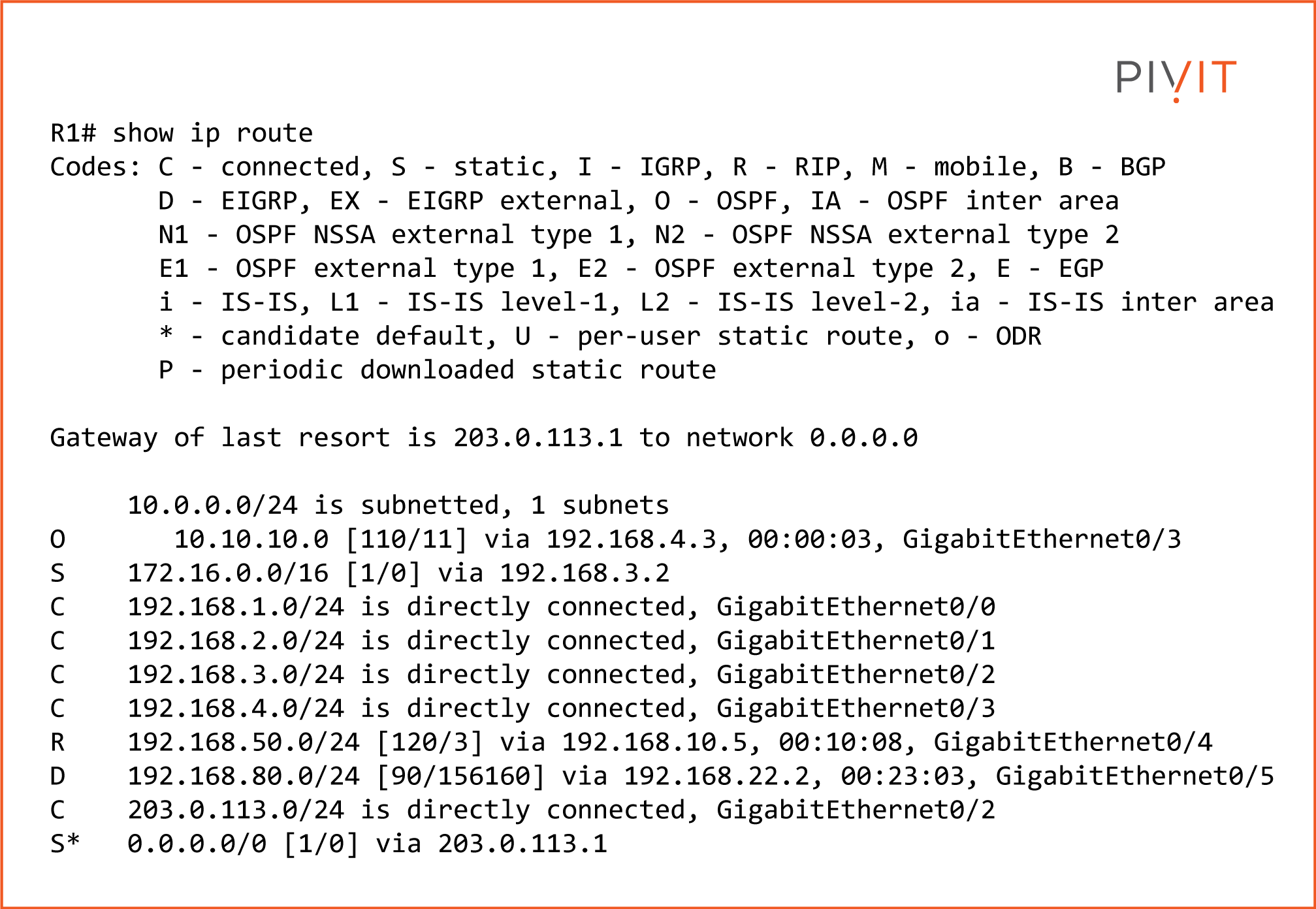
From the image above, you will notice that the routing table contains many entries, where some are directly connected networks, others learned through the OSPF, RIP, and EIGRP routing protocols, and a default route.
____________
Hardware Options
At PivIT, we bring options to the table that your traditional VAR won't, whether it is OEM options, financing options, maintenance options, and more. Click below to browse for a router and get started bringing options to your network!

____________
Directly Connected Networks
All directly connected networks are part of the routing table. After enabling an interface and assigning an IP address to it, the network is automatically added to the routing table. If an interface goes down, then the network is also removed from the routing table.
An active and properly configured interface creates two entries in the routing table. As you can see from the image below, each entry contains pieces of information, namely, a route source code, a destination network, and an outgoing or exit interface.
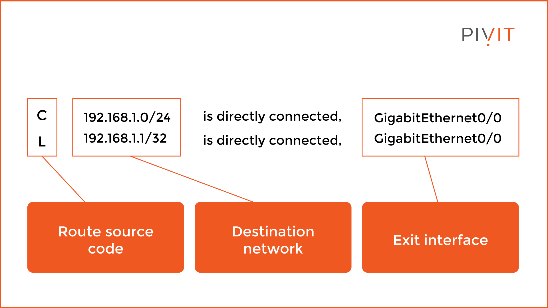
The route source code identifies how the route was learned. The “C” code identifies a directly connected network, while “L” identifies the IP address assigned to the interface.
The destination network for the “L” entry has a prefix of /32, while the “C” entry has a prefix corresponding to the network configured, in this case, /24. The exit interface is the one that is used for reaching the destination network.
Static Routes
Static routes are entries in the routing table that appear after you manually create them. They can point to a specific network or function as a default route pointing anywhere.
Since they are static, they do not automatically reconfigure themselves after a network change, so you have to perform that task on demand when required.
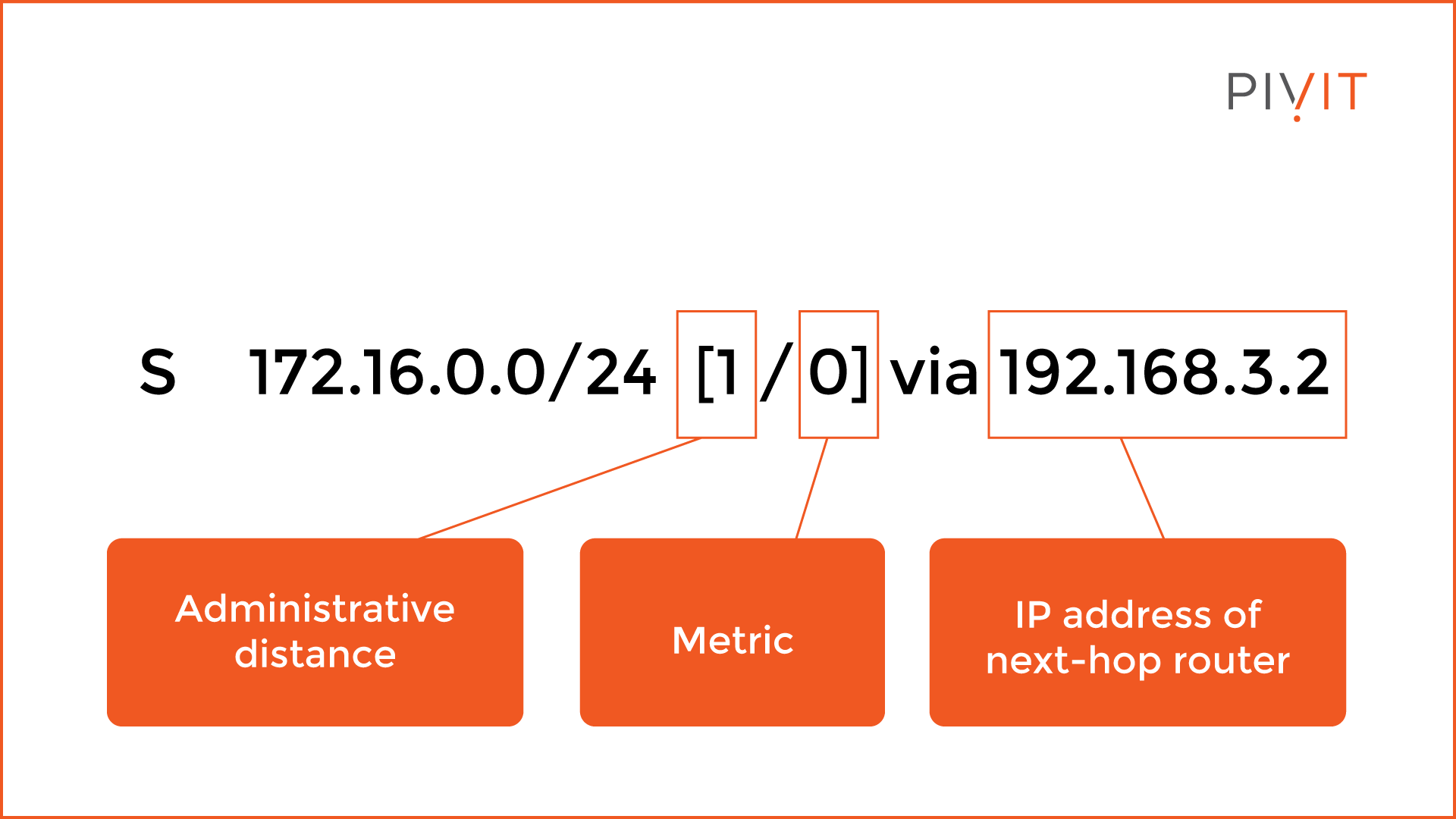
Each static route in the routing table is defined by several criteria. As you can see from the image above, the “S” code identifies the route to the destination network of 192.168.1.0/24 as static.
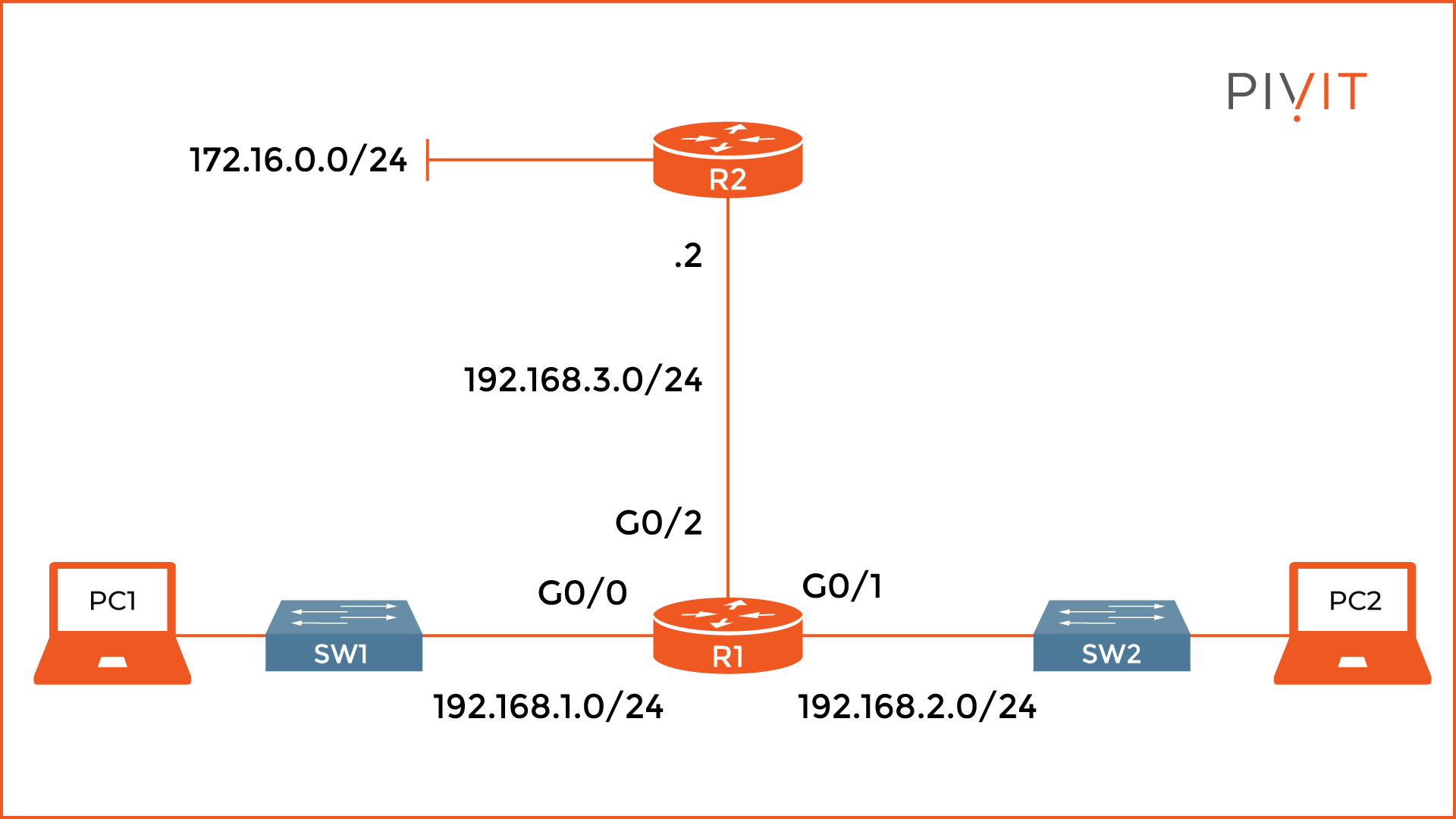
The administrative distance is 1 which is the default value, and the metric is 0, which is not as important as in the dynamic routing. At the end of the entry, there is information about the IP address of the next-hop router to which the packet is sent, in this case, 192.168.3.2.
Dynamic Routes
Since static routing works only in small networks and point-to-point links, dynamic routing must be used in large enterprise networks, campuses, or service providers. Routing protocols such as RIP, EIGRP, OSPF, and IS-IS exchange information about networks, and that data is inserted into the routing table as dynamic routes.
The best part about dynamic routing is the automatic recalculation performed by the routing protocols for each network change.
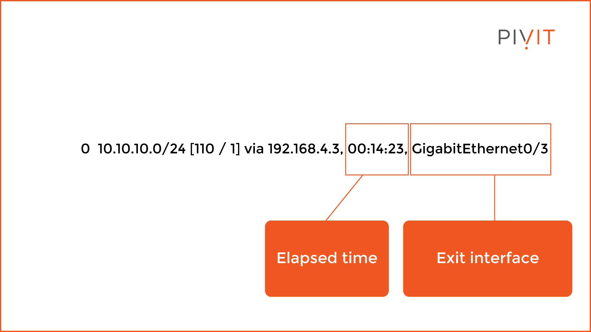
As you can see from the image above, the code in front of the destination network identifies the routing protocol through which the route was learned, such as in the example where “O” means OSPF.
The rest of the criteria is the same as with the static routes, with a difference that now the metric is extremely important for the path selection process, and the administrative distance is 110. Additionally, there is information about the time that elapsed since the network was learned, as well as the exit interface.
Default Routes
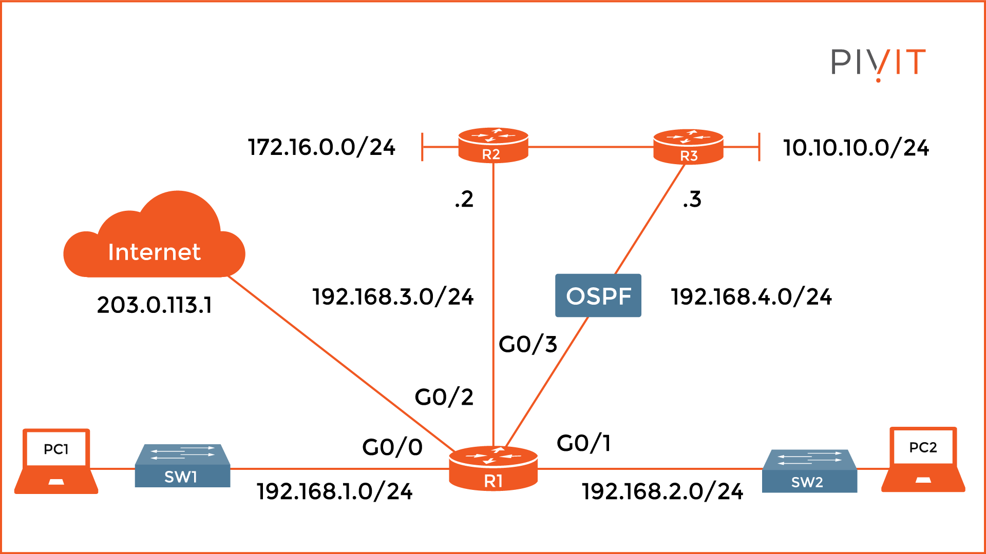
By default, routers do not have a default route. However, it is very important to configure one, so when the router has no information about the destination IP of the packet (such as a public IP on the internet), it will not discard it, but forward it to another router (default gateway) by simply using the default route. Additionally, a default route can be dynamically learned by using a routing protocol.

As you will notice from the image above, the default route functions as a gateway of last resort. The code identifies how it was learned, either statically or dynamically. In the example, it is “S” meaning statically configured.
However, the additional asterisk identifies the route as default. The destination network for the default route is always 0.0.0.0/0, meaning pointing to anywhere.
Even though the routing process looks simple, it consists of multiple steps. Once the router learns all possible routes to the networks in the topology, the path determination process starts.
First, based on the administrative distance (a lower value is better), routes from the best source are selected and used, and then they are additionally filtered out (if multiple paths to a single destination exist) based on the metric values (again, the lower value is better). In the end, only a single route to each network is included in the routing table.
Save Your Hardware and Engineering Resources
If your network is functional and there is proper communication between different parts of the network, it does not matter which routing approach you have implemented. However, using the most appropriate approach will always provide way more optimal routing and save resource consumption on the devices.
Speaking of saving on resources, PivIT offers SmartHands as part of its EXTEND product. Gain access to engineers around the globe to help build your wired and wireless networks without ever leaving your desk when you are tackling staff shortages, complex environments, office relocations, or emergency situations.