-1.png)
Welcome to Part 2 of the Cisco Adaptive Security Appliance (ASA) firewall active/standby configuration guide! In this article, we will focus on the deployment of the Cisco ASA firewall. The active/standby feature, as discussed in Part 1 of this series, has one simple goal: to provide uninterrupted network connectivity for users.
Looking to read Part 1 of this series? Go here
Using just a single ASA is a single point of failure and usually catastrophically reflects in the network when the device experiences common setbacks such as hardware issues, link/cable problems, or just a simple misconfiguration.
Therefore, using a second ASA to the primary one will provide a backup solution in case something goes wrong with the active unit. Although this solution is quite complex in its nature and offers a lot of tuning capabilities, we will focus only on the initial configuration required for the Active/Standby failover to operate.
Download the guide and refer back to it at any time!
In order to achieve that, we will take a look at two approaches, namely, using the Command Line Interface (CLI) and the Adaptive Security Device Management (ASDM) GUI.
Looking for a firewall device? See our overview of the Cisco ASA 5500 Series firewall here or get in touch with us to find the perfect match for your network.

Active/Standby Configuration Example
This section describes how to configure Active-Standby failover deployment between two Cisco ASAs. You can see in the image below that both ASAs are directly connected to each other using the GigabitEthernet0/2 interfaces operating as a LAN failover and stateful failover interface for synchronizing connection information for failover and hardware redundancy.
The network used on this link is 192.168.255.0/24. The ASA at the top is the primary/active (ASA1) unit, while the ASA at the bottom is the secondary/standby (ASA2) unit.
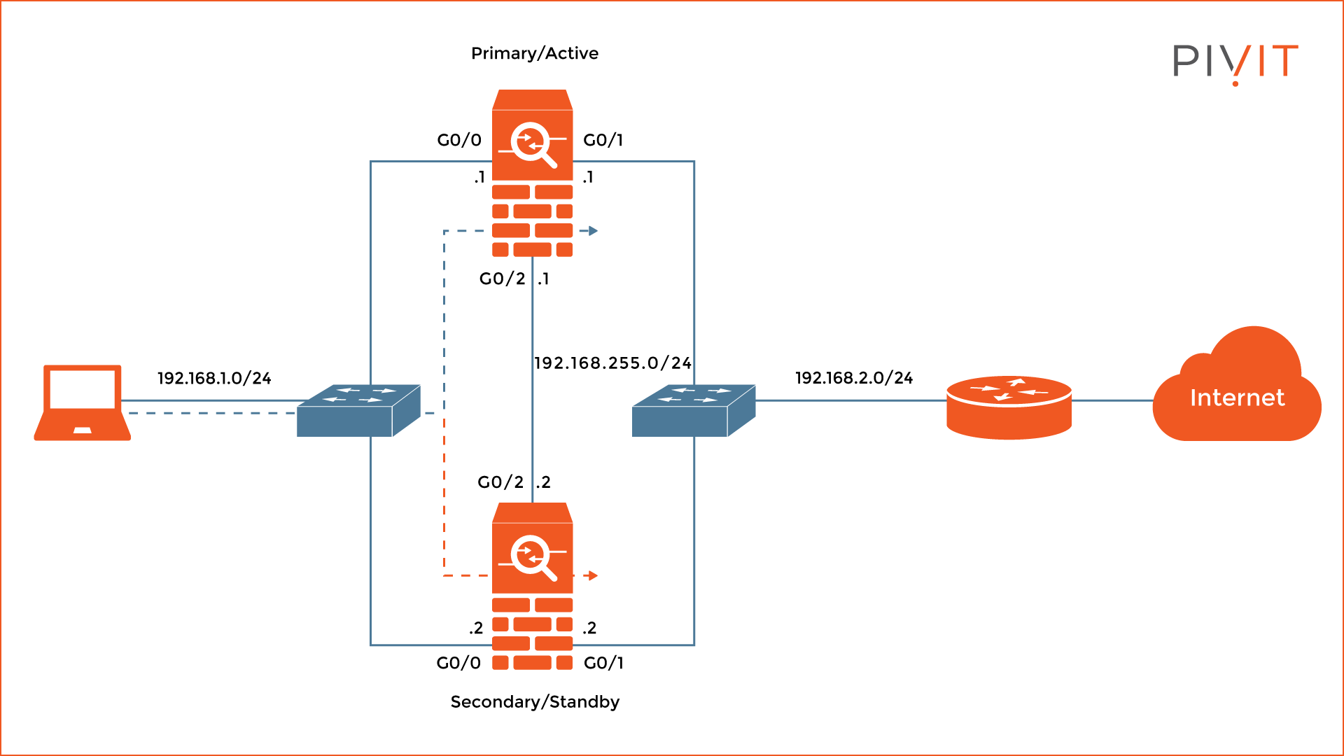
On the left of the ASAs is the internal network of 192.168.1.0/24 (“inside” security zone) where the computer is connected, while on the right is the outside network of 192.168.2.0/24 (“outside” security zone) where the exit router is available.
The internal interfaces on both ASAs are GigabitEthernet0/0, while the external interfaces connecting to the router are GigabitEthernet0/1.
Step-by-Step Active/Standby Failover Configuration
To configure Active/Standby failover on a Cisco ASA, the following configuration steps must be completed:
- Configure the Active/Standby failover on the primary device.
- Configure the Active/Standby failover on the secondary device.
- Verify the Active/Standby failover deployment.
1. Configure the Active/Standby Failover on the Primary Device
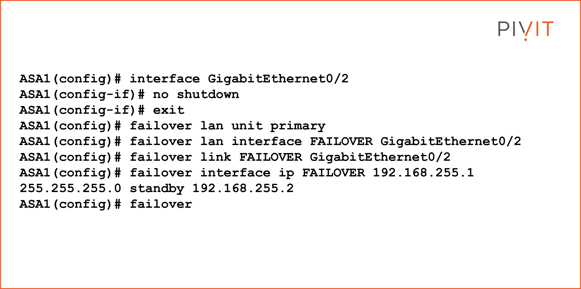
First, it is required to enable the GigabitEthernet0/2 interface that connects to the secondary ASA that will be used as a LAN and stateful failover link between the firewalls. Then, configuring the ASA as a primary unit will help in the selection of an active unit in the pair.
The next step is to configure the interface as a LAN failover interface, as well as a stateful failover interface. Lastly, configure the active and standby addresses on the failover link between the ASAs and enable the failover feature.
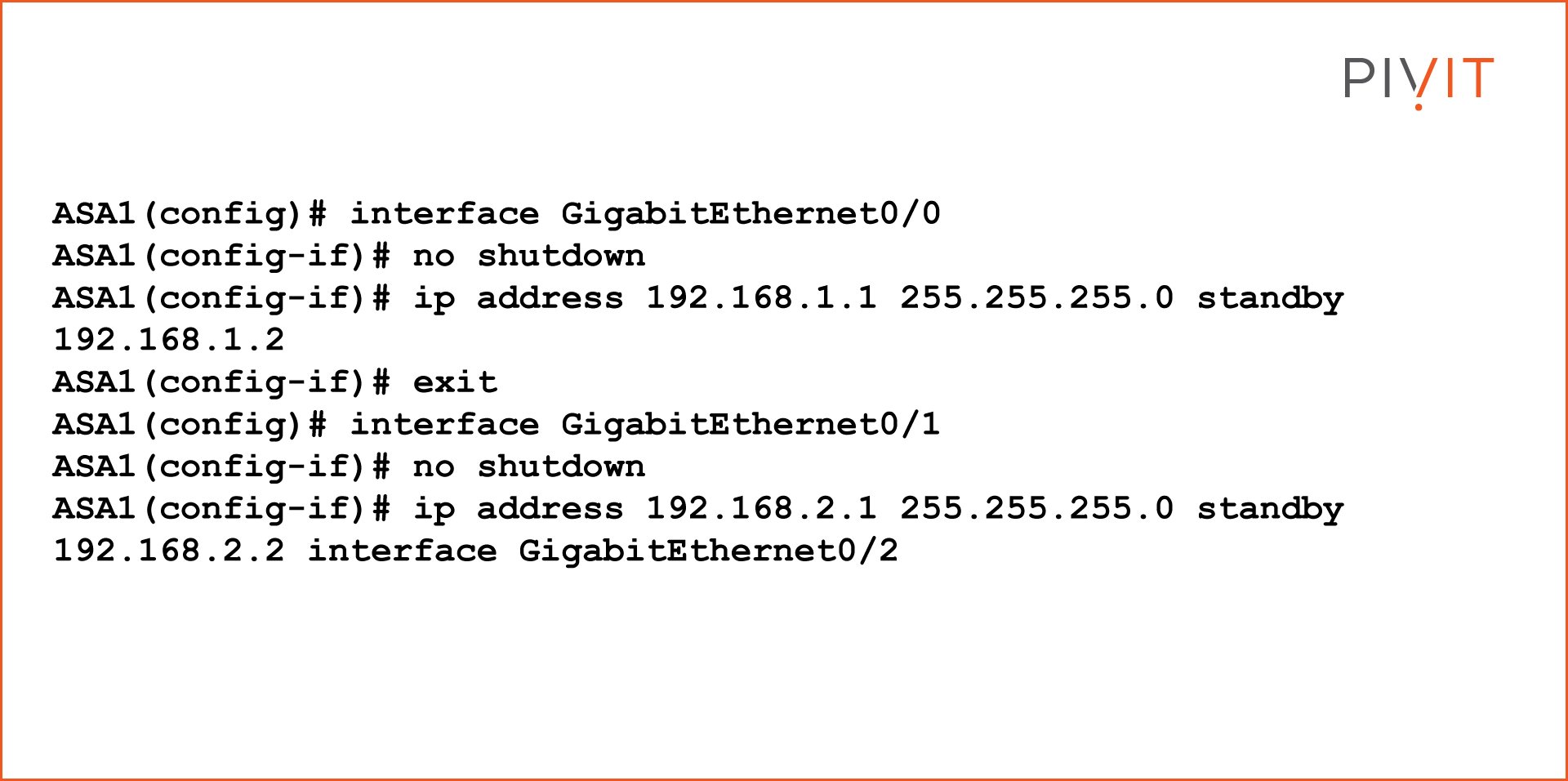
Once the basic configuration is done, enable the GigabitEthernet0/0 interface and define the active and standby IP addresses on the internal traffic-passing interfaces connecting to the computer.
Then, repeat the same procedure for the other interface, GigabitEthernet0/1; enabling the interface and configuring the active and standby IP addresses on the external traffic-passing interfaces on the ASA.
2. Configure the Active/Standby Failover on the Secondary Device
The configuration on the secondary ASA is almost identical to the one on the primary ASA, with one small difference in the configuration that makes the firewall operate as a secondary/standby unit.
First, enable the GigabitEthernet0/2 interface that connects to the primary ASA. Once enabled, it must be defined as a LAN failover interface, as well as a stateful failover interface.
On this firewall, the secondary role should be applied instead of the primary role. Also, configure the active and standby addresses on the failover link between the ASAs and enable the failover feature.

3. Verify the Active/Standby Failover Deployment
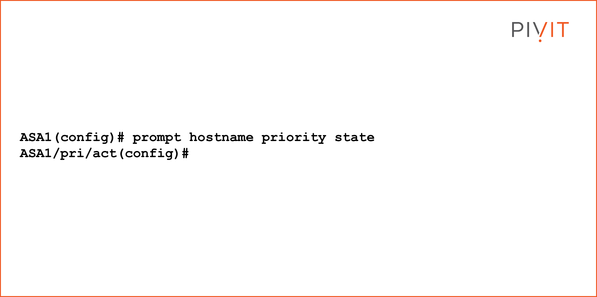
Once the configuration is replicated on both ASAs, they both use the same hostname. This means that every time you access the ASAs over a console, Secure Shell (SSH), or Telnet connection, it will not be easy to differentiate between the units being managed.
Therefore, it is recommended to change the CLI prompt to include additional information next to the hostname, such as the priority and state of the managed device.
The following command should be entered to customize the prompt:
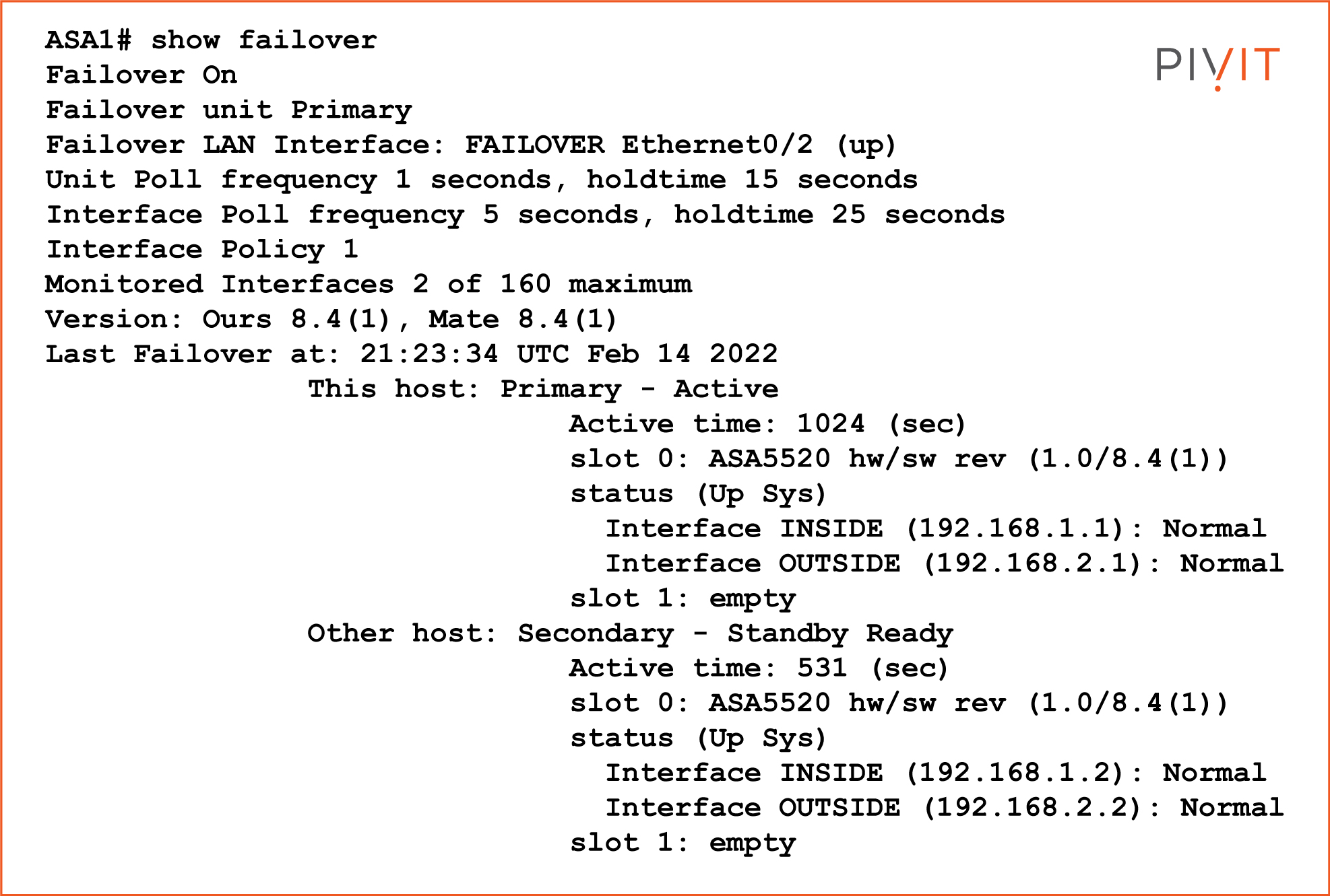
The “show failover” command should be used to verify that the failover deployment is configured and working properly. The following example displays the output of using the verification command:
Cisco ASDM Configuration Steps
Using the Cisco ASDM management tool is quite a popular choice among network engineers. Even though the CLI provides more options, configuring the Cisco ASA through a GUI is an easier and more straightforward approach that does not require the same amount of knowledge as using the CLI.
Two options are available for configuring Active/Standby failover; using the wizard which guides the user through all the necessary steps or manually configuring everything. Let’s cover the manual approach.
First, enable the failover feature, enable the interface for LAN failover and stateful failover, and define the role and the active and standby IP address.
Once the configuration is applied, the ASDM prompts for the IP address of the secondary ASA. When providing the IP address, the Cisco ASDM will automatically configure the secondary Cisco ASA with the same settings as those used on the primary, with one small difference of assigning the secondary role to the second ASA.
In this case, use the inside IP address of the secondary ASA. This step is optional, so you can go through the same steps as configuring the primary appliance and set up everything manually.
The last step is to configure the standby IP addresses on the active device for both the inside and outside interfaces. The active IP addresses are automatically inherited from the interface configuration of the Cisco ASA.
Whether you use the CLI or the ASDM approach comes down to personal preference. What counts is to configure the Cisco ASA firewalls correctly and verify that the Active/Standby failover feature works on both units when unpredictable issues occur. Only then can you be sure that there will be uninterrupted network connectivity for the users when something goes wrong on the firewalls and failover is performed.
If you're having any issues with the configuration of your Cisco ASA firewall, be sure to contact us for immediate assistance.