-1.png)
For uninterrupted network connectivity and knowledge of every single part of the network topology, the usage of dynamic routing protocols is an inevitable step. Unless there is a point-to-point or a hub-and-spoke topology where static routing is a proper fit, in any other network type and size (small, medium, or large), we heavily depend on the routing protocols.
There are many different internal routing protocols available today such as RIP, EIGRP, or IS-IS, with Open Shortest Path First (OSPF) being the most popular one among them. OSPF is a standard routing protocol developed more than 30 years ago that belongs to the link-state routing protocols family along with IS-IS.
Unsure if OSPF is the best interior routing protocol for your network?
Read our in-depth comparison here.
Additionally, OSPF is a classless routing protocol, thus allowing routers to exchange routing information about subnets instead of full classes only. In this article, we will look at the basics of OSPF, the benefits of using it, and a simple example of a single-area OSPF configuration.
If you'd like to learn more about multi-area configurations for OSPF, you can jump to part two of this series.
Discover the Basics of the OSPF Routing Protocol
OSPF as a link-state routing protocol identifies two parameters, the “link” representing the interface and the “state” representing the relationship of the interface to the neighboring router. Compared to the traditional distance vector routing protocols such as EIGRP or RIP, OSPF has the following advantages:
- More scalable approach.
- Efficient use of updates by sending trigger updates.
- Each router has a full map of the topology.
- Responds quickly to topology changes.
Download the guide and refer back to it at any time!
Also, OSPF relies on independent transport and not IP, has support for Variable Length Subnet Mask (VLSM) and authentication, and uses a simple approach for the calculation of the metric.
OSPF Data Structures
When OSPF is enabled on routers, hello packets will be sent to neighboring devices enabled for OSPF to form a neighbor adjacency. Once established, the neighbors are put into each neighbor’s database tables.
Next, they start exchanging link-state advertisements (LSA) to learn the complete topology of the network. All this information is stored in a special table called the link-state database (LSDB).
After the data is processed by the shortest path first (SPF) or Dijkstra algorithm, only the best routes to each network will be placed in the routing table.
When routers exchange LSAs, five different types of OSPF packets are involved in the process, each one with a different purpose:
- Hello: For discovering and maintaining the neighbor relationship.
- Database Description (DBD): Contains a summary of the LSDB.
- Link State Request (LSR): For requesting information about a missing route.
- Link State Update (LSU): Update information for a received LSR packet.
- Link State Acknowledgement (LSAck): Acknowledgement for the received DBD, LSR, and LSU packets.
Before we continue, ask yourself a couple of questions:
Do I have the time to handle configurations?
Do I have the bandwidth to configure my devices?
If you answered "No" to these questions, let PivIT handle the OSPF configuration on your network with EXTEND. Hire an engineer to take on these basic configurations and more. Click below to learn more about SmartHands.

Hierarchical Structure of OSPF
OSPF uses a two-layer network hierarchy, consisting of an Autonomous System (AS) that represents a collection of networks under a common administration that usually shares a common routing strategy, and an Area representing multiple grouped networks.
When implementing OSPF, Area 0 or the backbone area must be defined and is usually enough for normal operations in a network. However, in large enterprises, there is a need for a multi-area approach. In such a design, all additional areas must be directly connected to the backbone area, which limits the flexibility of OSPF.
Even though the number of routers used per single area depends on many factors, the general recommendation is to have no more than 50. An area usually represents a location, building, department, or anything that has a meaning to the OSPF design plan.
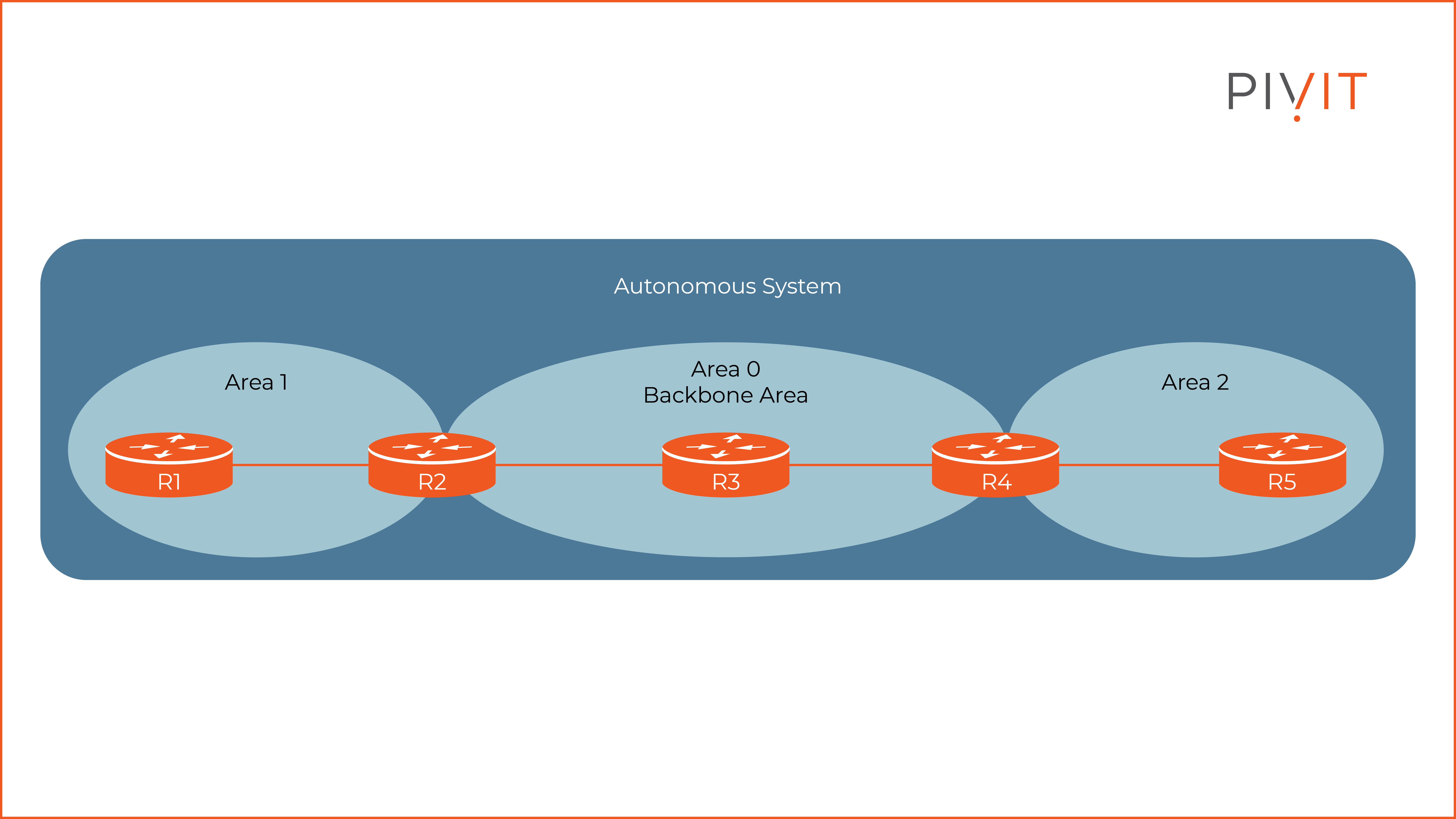
The image above shows an example of an AS and multiple OSPF areas in it. Depending on the location within the AS, the routers will have corresponding names and perform different roles.
Routers that belong in Area 0 are known as backbone routers such as R2, R3 (pure backbone router), and R4. R1 and R5 routers that belong in Area 1 and 2 are called internal routers.
Finally, R2 and R4 routers that are connected to more than one area are known as area border routers (ABR) and play a key role in a multi-area design.
If you are having trouble with the OSPF configuration, send PivIT a request or connect with our Team in real-time using our chat feature. Know how to configure OSPF but you're in need of a new router? Click below to view your options!

Establishing OSPF Neighbor Adjacencies
Before routers start sharing OSPF information about the networks they know about, they must first form neighbor adjacencies by exchanging hello packets on all OSPF-enabled interfaces.
Once the adjacency is established, they continue exchanging hello packets on the multicast IPv4 address of 224.0.0.5 to maintain the neighbor relationship.
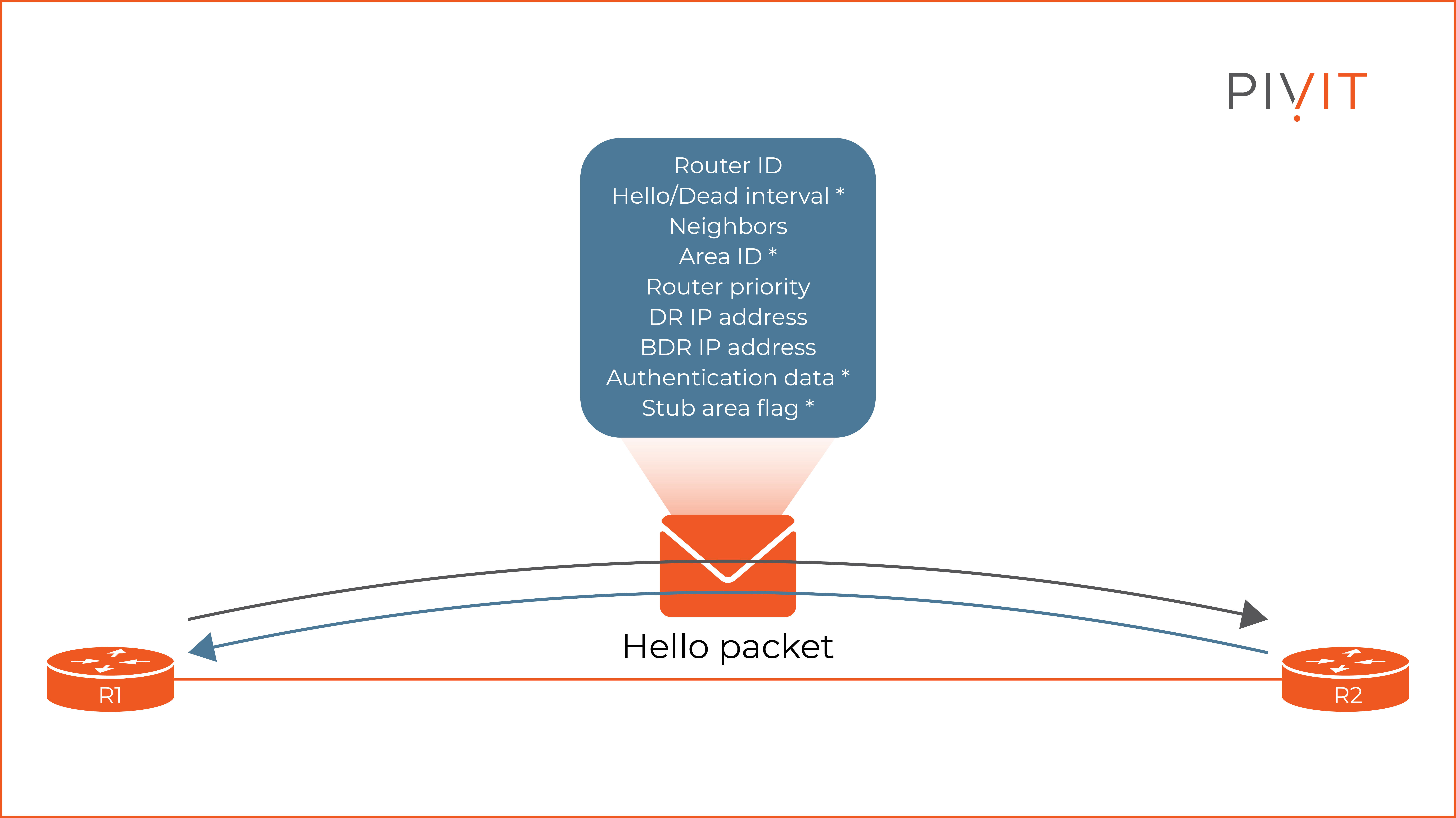
The image above shows the information included in each hello packet exchanged. The information marked with a * must match on both routers to form an OSPF relationship.
The “router ID” uniquely identifies each router in the OSPF network. The “hello/dead interval” (by default 10/40 seconds) defines the intervals that the hello packets are sent and the period after the neighbor is considered as down.
The “neighbors” is a list containing the router IDs for each neighbor known to the router. The “area ID” represents the area in which the router belongs. The “router priority” is a number used for the selection of a designated router (DR) and a backup designated router (BDR).
The “authentication data” is optional. The “stub area flag” identifies the type of area in which that router belongs.
OSPF Metric Calculation
The metric is a value that identifies the quality of a route. For OSPF to select the best route to each network, it must first calculate the metric for each interface and then find the total sum of all routes towards the destination.
The calculation of the OSPF metric is quite a simple process and is based on the bandwidth of the interface. The metric is called cost when using OSPF. On Cisco devices, the formula to calculate the OSPF cost is:
cost = reference bandwidth (100mbps) / interface bandwidth
The smaller the cost, the better the path. However, it is important to note that the cost cannot go below 1. As a result, every link faster than 100 Mbps will be identified as equally good according to OSPF.
Therefore, the reference bandwidth needs to be changed to a value equal to or higher than the fastest link in the topology to ensure an accurate calculation.
Single-Area OSPF Configuration Example
Although OSPF supports a lot of tuning and additional miscellaneous features, we will only go through the basic configuration to establish an OSPF neighbor adjacency between two routers in Area 0 and verify the learning of networks through the routing protocol.
The image below shows the topology that will be used in this example for configuring OSPF between routers R1 and R2 in Area 0.

Assuming that interfaces on both routers are already configured with IP addresses and are enabled, all that needs to be done is to enable the OSPF process and then start OSPF on the desired interfaces.
Additionally, a router ID can be configured manually so that the routers are easily recognizable among administrators.

The following commands can be used to verify that OSPF is enabled on the correct interfaces, to check everything is running properly, and to ensure the neighbor adjacency has been established between the routers.
Finally, to verify that the routers are learning networks through OSPF, the “show ip route” command can be used to check if there are any OSPF routes included in the routing table.
.png?width=8000&name=8%20(1).png)
Is OSPF a Good Fit for Your Network?
OSPF is the most popular routing protocol in networks today because it is an open standard, easy to configure, offers a lot of additional tuning features, has fast convergence, and can be implemented in large networks.
Once the basics are learned and satisfactory knowledge is gained, the implementation of OSPF can start. However, keep in mind that a good network design is a mandatory step before starting with the OSPF configuration. The reason for this is that as a network grows with the addition of more areas, the flexibility of the OSPF becomes limited. To see how OSPF can reach multi-area deployments, view this configuration guide.
____________
Was this configuration guide helpful? We have more routing configuration guides available! Click here to see more configuration guides.
____________